Antenna device and mobile terminal having the same

a mobile terminal and antenna device technology, applied in the field of mobile terminals, can solve the problems of difficult miniaturization of the mobile terminal, difficult to independently control the parameter values which determine the antenna characteristics, and complex structure, so as to reduce prevent the lowering of the performance of the antenna device, and reduce the effect of the electromagnetic influence on the antenna devi

Active Publication Date: 2016-05-10
LG ELECTRONICS INC
View PDF21 Cites 4 Cited by
  • Summary
  • Abstract
  • Description
  • Claims
  • Application Information

AI Technical Summary

Benefits of technology

[0035]Secondly, as the slot of the antenna device is formed at a gap required in the mobile terminal due to an allowance (tolerance), an inner space of the mobile terminal can be utilized in a more efficient manner.
[0036]Thirdly, even if the antenna device is disposed near the conductive case, the first conductive case is separated from the second conductive case. Under such configuration, an electromagnetic influence on the antenna device can be reduced, and thus lowering of performance of the antenna device can be prevented.
[0037]Fourthly, as a user's contact, which may influence on the antenna device, is performed only on the second conductive case. This can reduce lowering of performance of the antenna device due to a body effect.

Problems solved by technology

However, such antennas have a complicated structure, and it is difficult to independently control parameter values which determine antenna characteristics such as a resonance frequency, a bandwidth and a gain.
This may cause a difficulty in miniaturizing the mobile terminal.

Method used


Image

  • Antenna device and mobile terminal having the same
  • Antenna device and mobile terminal having the same
  • Antenna device and mobile terminal having the same

Examples


first embodiment

[0158]FIG. 6A is a conceptual view showing an antenna device of a mobile terminal according to the present invention, FIG. 6B is a conceptual view showing an example where a stub has been added to the antenna device of FIG. 6A, and FIG. 6C is a view showing voltage standing wave ratios (VSWR) of the antenna devices of FIGS. 6A and 6B.

[0159]As shown in FIG. 6A, the antenna device 300 comprises a first member 310, a second member 320, a feeding portion 330 and a feeding extension portion 360.

[0160]Each of the first member 310 and the second member 320 may be configured as a conductive member, and the first member 310 and the second member 320 define a slot (S) of the antenna device 300. That is, a space between the first member 310 and the second member 320 serves as a slot (S) of the antenna device. An open part of the slot (S) is called an opening 350. A closed part of the slot (S), due to connection between the first member 310 and the second member 320, is called a connector 340.

[...

second embodiment

[0207]FIGS. 8A and 8B are conceptual views showing an antenna device of a mobile terminal according to the present invention.

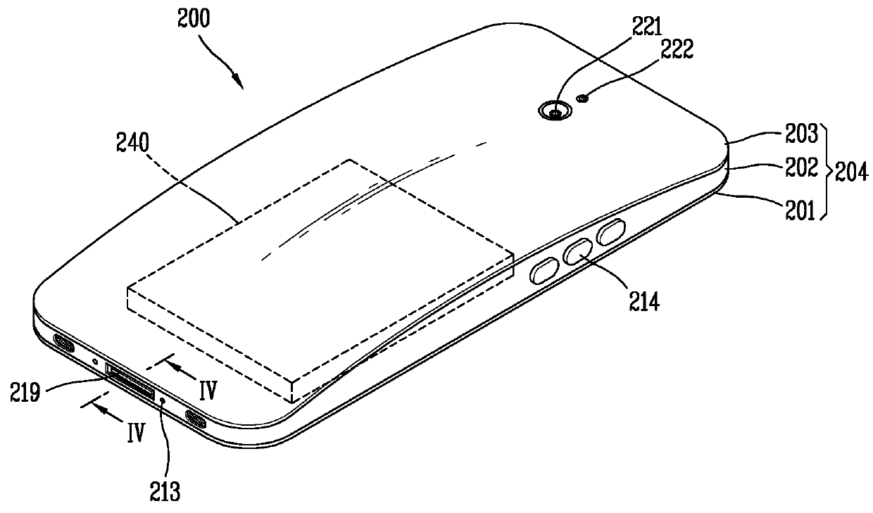
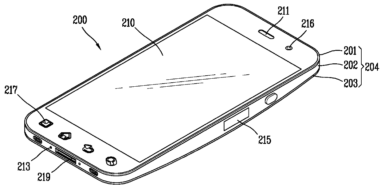
[0208]Referring to FIG. 8A, the antenna device comprises a first member 1110 and a second member 1120. The first member 1110 and the second member 1120 are spaced from each other, and form a slot (S) of which one side is open. The first member 1110 is part of a case which forms an appearance of the terminal body. The case may be a conductive member which forms a side appearance of the mobile terminal. The conductive member may be part of the front case 201 or the rear case 202.

[0209]The second member 1120 may be implemented as a frame for supporting inside of the mobile terminal. Alternatively, the second member 1120 may be implemented as a flexible printed circuit board (FPCB) for transmitting a signal generated from the user input unit to the controller, or an FPCB for transmitting a signal input and output from the socket 219 to the controller, the socket 2...

third embodiment

[0216]FIGS. 9A to 9C are conceptual views showing an antenna device of a mobile terminal according to the present invention, and antenna devices according to comparative embodiments. In this embodiment, a plurality of antennas are formed. A first antenna device may operate as the aforementioned slot antenna, and a second antenna device may operate as a monopole type antenna, a dipole type antenna, or a PIFA type antenna.

[0217]As shown in FIG. 9A, a first member 1210 and a second member 1220 form a slot (S) of the antenna device. For instance, the first member 1210 may be implemented as a flexible printed circuit board (FPCB) for transmitting a signal generated from the user input unit to the controller. The second member 1220 may be implemented as a frame for supporting inside of the mobile terminal.

[0218]The first antenna device is fed by the feeding portion 1230 connected to a circuit board 1250 by a coaxial cable. A feeding extension portion 1260 extends from the first feeding po...


PUM


Abstract

A mobile terminal comprises: a terminal body having an upper part and a lower part; and an antenna device disposed on the upper part or the lower part of the terminal body, and configured to transmit and receive radio signals, wherein the antenna device comprises: a first member and a second member which form a slot of which one side is open; a feeding portion having one end connected to one of the first member and the second member such that the antenna device resonates in a first frequency band, and forming an electric field in the slot; and a feeding extension portion extending from the feeding portion such that the antenna device resonates in a second frequency band.

Description

CROSS-REFERENCE TO RELATED APPLICATION[0001]Pursuant to 35 U.S.C. §119(a), this application claims the benefit of earlier filing date and right of priority to Korean Application No. 10-2012-0066744, filed on Jun. 21, 2012 and Korean Application No. 10-2012-0133296, filed on Nov. 22, 2012. The contents of all these applications are incorporated by reference herein in their entirety.BACKGROUND OF THE DISCLOSURE[0002]1. Field of the Disclosure[0003]The present disclosure relates to a mobile terminal, and particularly, to a mobile terminal having an antenna device capable of transmitting and receiving (transceiving) radio signals.[0004]2. Background of the Disclosure[0005]A mobile terminal is a device that can be carried around and has one or more functions such as to perform voice and video call communications, inputting and outputting information, storing data, and the like.[0006]As functions of the mobile terminal become more diversified, the mobile terminal can support more complica...

Claims


Application Information

Patent Timeline
Patent Type & Authority Patents(United States)
IPC IPC(8): H01Q13/10H01Q1/24H01Q21/28H01Q5/307H01Q5/10
CPCH01Q13/106H01Q1/243H01Q5/307H01Q13/10H01Q21/28H04M1/026H04M1/0277
Inventor JUNG, BYUNGWOONLEE, JAEWOOKWAK, DAEYONGRHYU, HANPHILRHO, SUNGJUNG
Owner LG ELECTRONICS INC
Why Eureka
Try Eureka