Check patentability & draft patents in minutes with Patsnap Eureka AI!

Logical unit address assignment

a logical unit and address technology, applied in the field of memory devices, can solve the problem of limited number of logical units that can be packaged within the memory device, and achieve the effect of reducing the number of logical units

Active Publication Date: 2016-07-12
MICRON TECH INC
View PDF47 Cites 1 Cited by
  • Summary
  • Abstract
  • Description
  • Claims
  • Application Information

AI Technical Summary

Problems solved by technology

In addition, the number of logical units that can be packaged within a memory device is limited by the number of unique logical unit addresses that can be assigned to the logical units, and thus by the number of address control signals that the logical unit is capable of receiving.

Method used


Image

  • Logical unit address assignment
  • Logical unit address assignment
  • Logical unit address assignment

Examples


Embodiment Construction

[0020]In the following detailed description, reference is made to various embodiments of the invention. These embodiments are described with sufficient detail to enable those skilled in the art to practice them. It is to be understood that other embodiments may be employed, and that various structural, logical and electrical changes may be made. In addition, reference is made to various processes including multiple steps. It should be understood that these steps need not be performed in the order that they are listed, unless specifically stated as such.

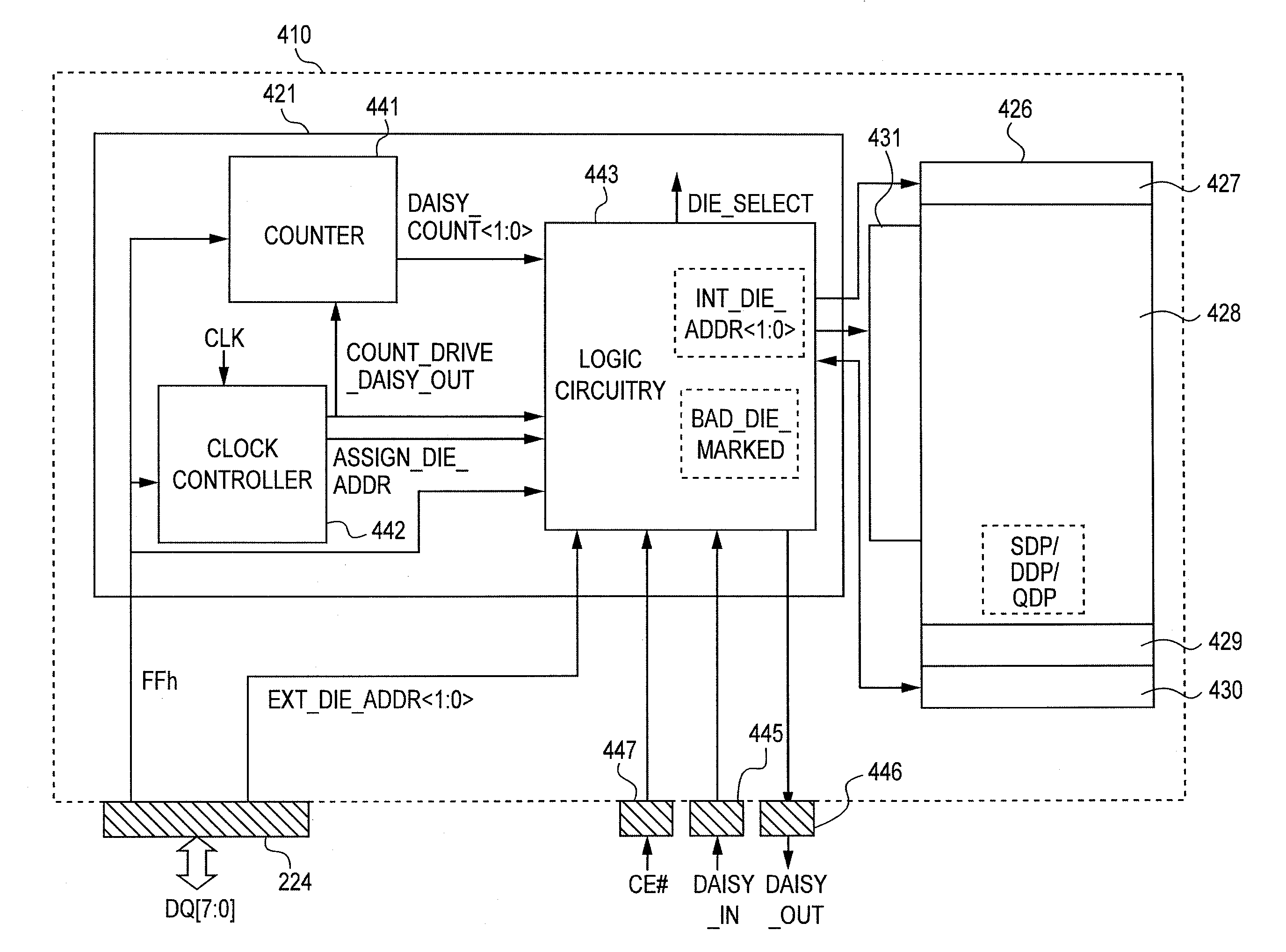
[0021]Described embodiments include a logical unit for an apparatus, such as, for example, a circuit, a device (e.g., a memory device), or a system (e.g., a memory system) that is configured to assign a logical unit address during initialization through a daisy-chain technique. By reducing the number of external contacts required for assigning the logical unit address, the required surface area for the logical unit can be reduced. In ...


PUM


Abstract

Described embodiments include logical units within a memory device with control circuitry configured to assign a logical unit address to the logical unit. Apparatus including a plurality of the logical units arranged in a daisy chain configuration and methods of assigning logical unit addresses to the logical units are also disclosed.

Description

TECHNICAL FIELD[0001]Described embodiments relate to memory devices, in which a memory package contains a plurality of addressable memory chips.BACKGROUND OF THE INVENTION[0002]In a memory system for a computer or for other electronic devices, one or more memory devices are typically coupled to a memory controller via a shared bus. Memory devices may include volatile memory devices such as random-access memory (RAM), dynamic random access memory (DRAM), and synchronous dynamic random access memory (SDRAM), and / or non-volatile memory devices such as NAND flash memory, NOR flash memory, read only memory (ROM), Electrically Erasable Programmable ROM (EEPROM), Erasable Programmable ROM (EPROM), phase change random access memory (PCRAM), resistive random access memory (RRAM), and magnetic random access memory (MRAM), such as spin torque transfer random access memory (STT RAM).[0003]A memory system can include a number of discrete memory devices. Each memory device is typically provided a...

Claims


Application Information

Patent Timeline
Patent Type & Authority Patents(United States)
IPC IPC(8): G06F12/00G11C29/00G06F13/00G06F13/28G06F13/42
CPCG06F13/4247G11C29/883
Inventor LEE, JUNEGRUNZKE, TERRY M.NOBUNAGA, DEAN
Owner MICRON TECH INC
Features
  • R&D
  • Intellectual Property
  • Life Sciences
  • Materials
  • Tech Scout
  • Unparalleled Data Quality
  • Higher Quality Content
  • 60% Fewer Hallucinations
Learn More