Car provided with a rear spoiler

a rear spoiler and car technology, applied in the direction of vehicle components, vehicle body streamlining, propulsion parts, etc., can solve the problems of reduced rear visibility, high production cost, and relatively bulky rear wing elements, and achieve easy and economical production, good aerodynamic efficiency

Active Publication Date: 2017-02-28
SPAN FERRARI SPA
View PDF17 Cites 4 Cited by
  • Summary
  • Abstract
  • Description
  • Claims
  • Application Information

AI Technical Summary

Benefits of technology

[0006]The purpose of the present invention is to provide a car provided with a rear spoiler, said car having good aerodynamic efficiency in the rear part and, at the same time, being easy and economical to produce.

Problems solved by technology

However, a rear wing is a relatively bulky element and may be associated with several drawbacks (such as higher production costs, reduced rear visibility, restricted access to the rear compartment, which may house the engine or a boot).

Method used


Image

  • Car provided with a rear spoiler
  • Car provided with a rear spoiler
  • Car provided with a rear spoiler

Examples


Embodiment Construction

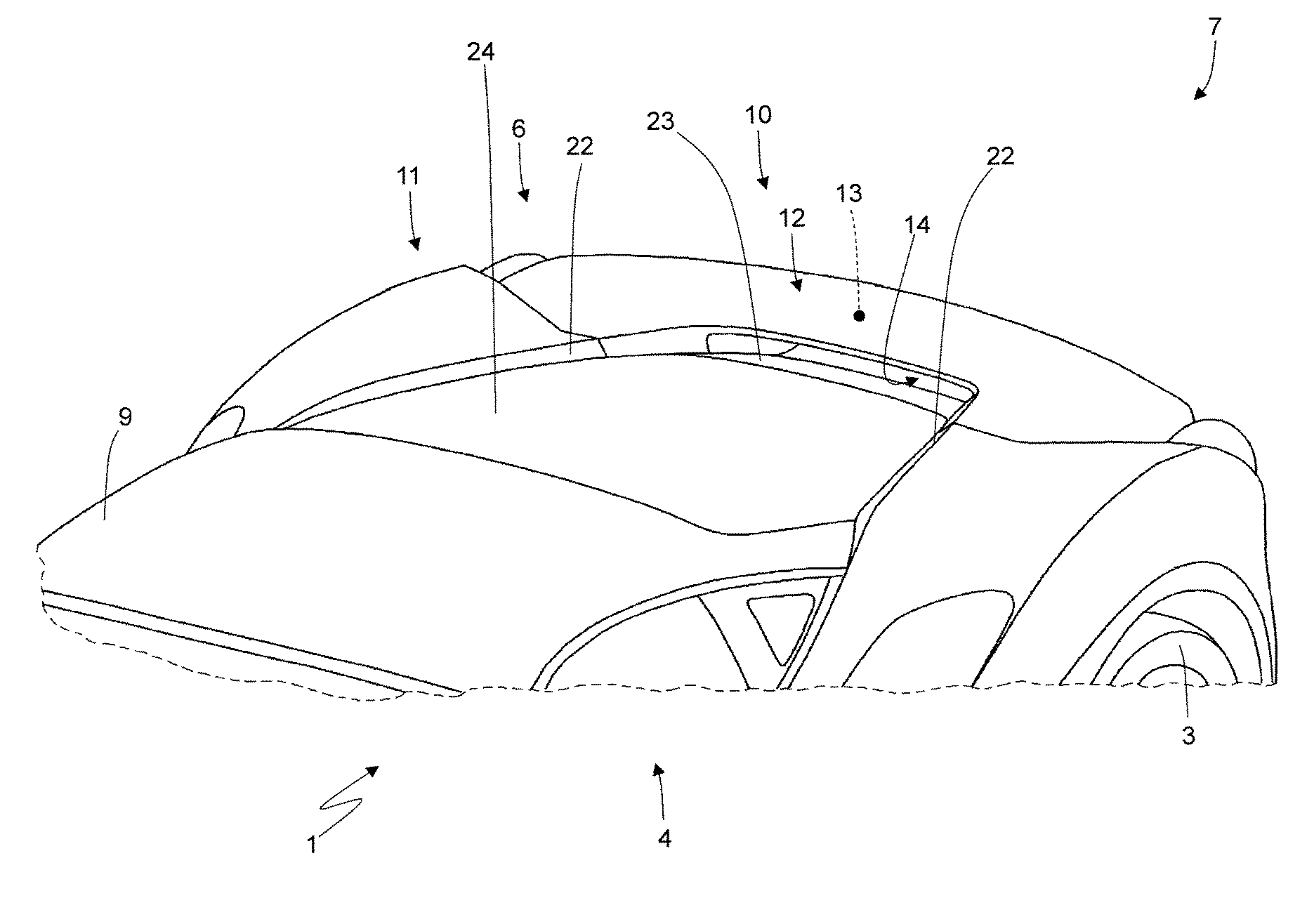
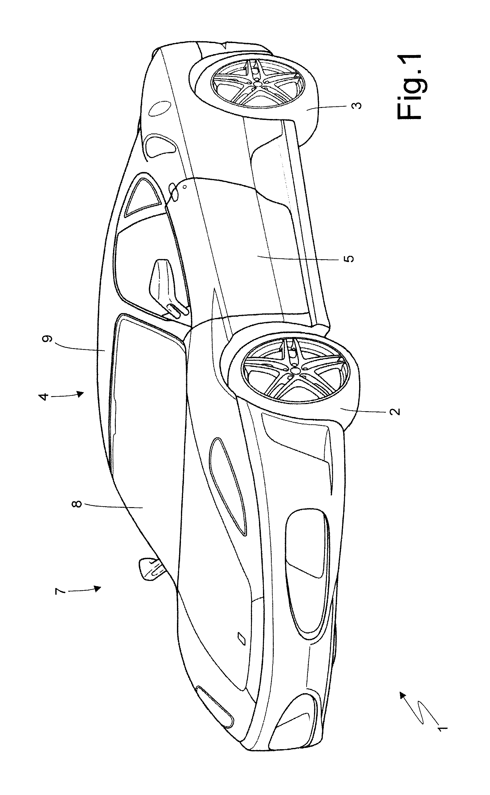
[0014]In FIG. 1, reference numeral 1 globally denotes a car powered by means of an internal combustion engine arranged in a central position. The car 1 comprises a chassis, which supports the internal combustion engine, a pair of front wheels 2, and a pair of rear wheels 3.

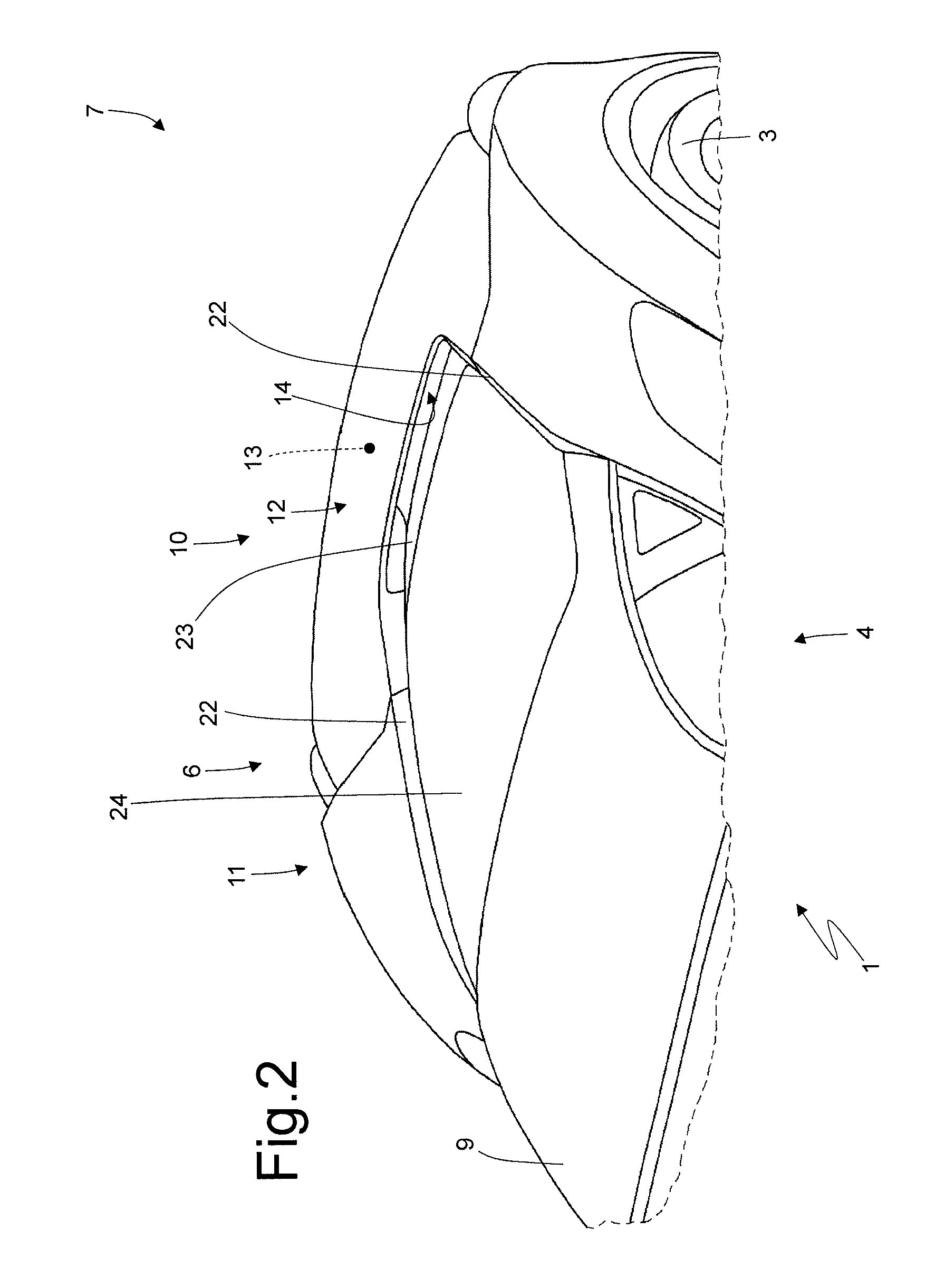
[0015]Between the front wheels 2 and the rear wheels 3 there is a passenger compartment 4 which is accessed through a pair of doors 5. Behind the passenger compartment 4 and in a central position there is an engine compartment 6 (partially illustrated in FIGS. 2, 3 and 4) which houses the internal combustion engine.

[0016]The chassis is covered by a car body 7 which comprises, among other things, the doors 5, a transparent windscreen 8 which delimits the passenger compartment 4 at the front and a roof 9 that delimits the passenger compartment 4 on the upper side. Connected to the car body 7 is a rear spoiler 10 (illustrated in FIGS. 2, 3 and 4) which is a continuation of the car body 7 and comes into contact with s...


PUM


Abstract

A car comprising a car body and a rear spoiler that projects from the outline of the car body to deflect the air flow upwards so that the air flow skims over an upper surface of said rear spoiler. The rear spoiler comprises a through aerodynamic duct, which starts in an inlet opening arranged in correspondence with an initial end of the rear spoiler and ends in an outlet opening arranged in correspondence with a final end of the rear spoiler, so that a part of the air flow hitting the rear spoiler flows above the rear spoiler, skimming over the upper surface of the rear spoiler, and the remaining part of the air flow hitting the rear spoiler flows through the rear spoiler crossing the aerodynamic duct.

Description

FIELD OF THE INVENTION[0001]The present invention relates to a car provided with a rear spoiler.DESCRIPTION OF THE RELATED ART[0002]In high-performance cars the aerodynamics are designed to generate a strong negative lift (i.e., a strong downforce) while at the same time reducing drag to a minimum. Thus, the aerodynamic efficiency of a car is measured as a function of the ratio between the negative lift and the corresponding drag: the higher this ratio, the greater the aerodynamic efficiency of the car.[0003]In order to increase the negative lift on the rear axle, a method known in the prior art consists of mounting a rear spoiler, i.e., an aerodynamic element projecting from the outline of the car body that deflects the air flow upwards. It is important to note that the rear spoiler is an element that extends upwards from the car body and constitutes a seamless extension of said car body; thus, the air flow is forced to bypass the rear spoiler, i.e. to pass over the rear spoiler wi...

Claims


Application Information

Patent Timeline
Patent Type & Authority Patents(United States)
IPC IPC(8): B62D37/02B62D35/00B60K8/00
CPCB62D37/02B62D35/007B60K8/00B62D35/00Y02T10/82
Inventor CARDILE, ENRICO
Owner SPAN FERRARI SPA
Why Eureka
Try Eureka