
Occluder

a technology of occluder and splint, applied in the field of occluder, can solve problems such as severe damag

Active Publication Date: 2017-05-16
CARAG AG
View PDF25 Cites 0 Cited by
  • Summary
  • Abstract
  • Description
  • Claims
  • Application Information

AI Technical Summary

Benefits of technology

The patent describes a device used to close off a passage in the body, such as a heart defect or blood vessel, by using a fixation structure and a jacket. The fixation structure is made of elongate members that can be bent to fit the shape of the body's passage, and it is held in place by the jacket. The jacket prevents parts of the fixation structure from breaking away and wandering through the body. The jacket also helps to encourage the growth of endothelial cells, which can further enhance the device's effectiveness. The patent also describes a preferred embodiment where the fixation structure is made up of two occluding bodies, each with its own fixation structure and locking unit, to ensure a secure closure of both sides of the passage. The elongate members can move relative to the jacket to avoid disturbing the fixation structure during expansion. Sewing the jacket onto the elongate members is one simple way to connect the two securely. Overall, the patent provides technical improvements and enhancements for devices used for closing off passages in the body.

Problems solved by technology

Small parts which would otherwise break from the occluder and be transported in other parts of the human body, may cause some severe damage.

Method used


Image

  • Occluder
  • Occluder
  • Occluder

Examples


second embodiment

[0067]FIG. 10 shows the inventive occluder according to a The elongate members 1 are enveloped in jackets 6′ and 7′ each. The jackets 6′ are arranged between first holder 2 and first membrane 4. The second jackets 7′ are arranged between second holder 3 and second membrane 5. Between the two membranes 4, 5, the elongate members 1 are free and not encapsulated. Preferably the elongate members 1 can still move free relative to the jackets 6′, 7′.

third embodiment

[0068]FIG. 11 shows the inventive occluder. Here a long jacket 6″ which extends from the first to the second holder 2, 3 encapsulates at least approximately the whole length of each elongate member 1. The bushes 10 are also encapsulated within this jacket 6″. Once again the elongate member 1 can preferably still move relative to his jacket 6″ in its longitudinal direction. The long jacket 6″ can also be made of more than one part, for example three parts, so that the jacket is divided into three pieces by the two membranes 4, 5.

fourth embodiment

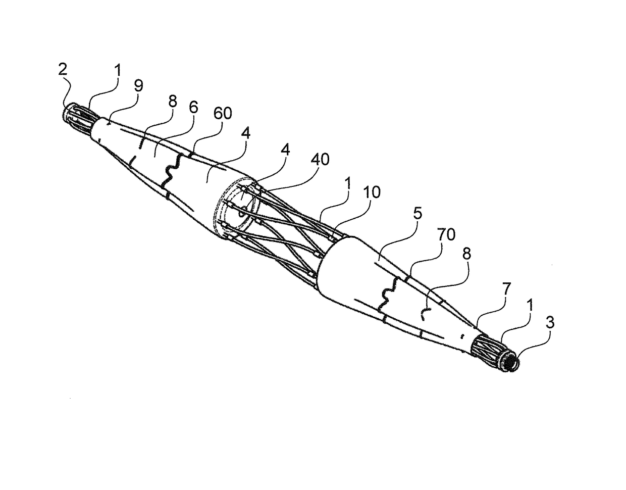
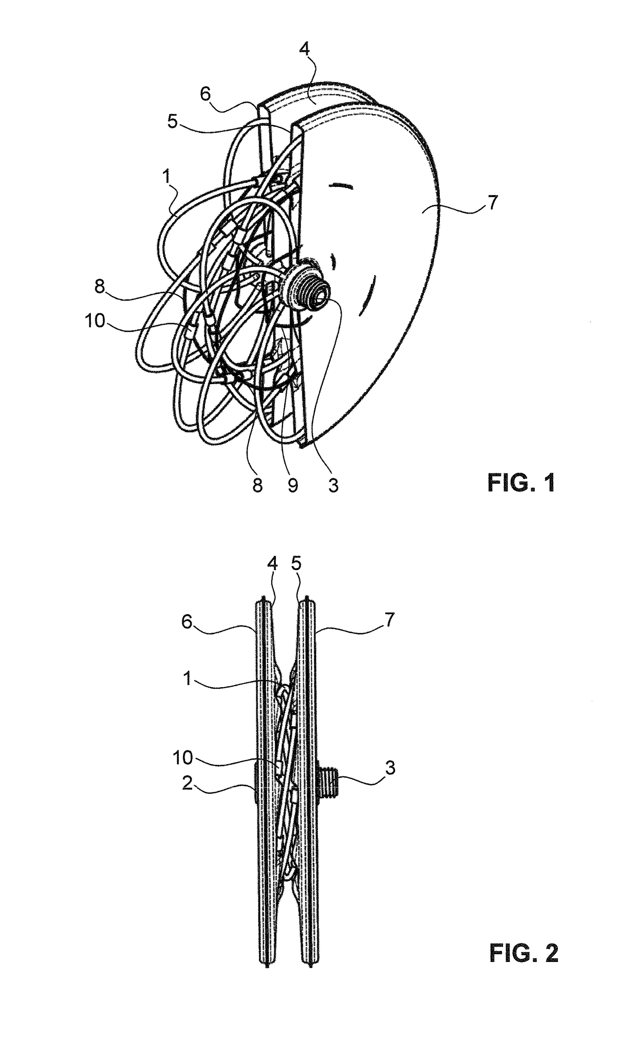
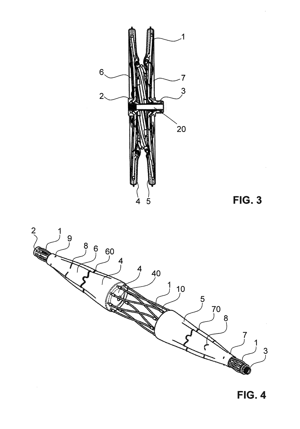
[0069]FIGS. 13 to 15 show the inventive occluder. This embodiment comprises the first and second jackets 6, 7, enveloping the two fixations structures on the distal and the proximal side of the occluder. These jackets 6, 7 are sleeves, arranged around the first and third portion of the bunch of elongate members 1. The jackets 6, 7, are preferably sewed to the elongate members 1 and to the membranes 4, 5. In addition this embodiment comprises a multiple of third jackets 6′, arranged between the first and the second membrane 4, 5, wherein these third jackets 6′ surround a single elongate member 1 each. As can best be seen in FIG. 15, they preferably only envelop the elongate members 1 partially, i.e. only between the two membranes 4, 5. Preferably, they are held in place by the threads 10 or the membranes 4, 5 themselves. The remaining parts of the elongate members 1 are enveloped as a bunch by the first and second jackets 6, 7.

[0070]The occluder according to the invention ensures tha...


PUM


Abstract

An Occluder for occluding a passage in a circulatory system comprises at least one occluding body (4), for occluding the passage, an expanding unit (1) comprising at least one fixation structure for fixing the occluding body (4, 5) within the passage, wherein at least a part of the expanding unit (1) is expanding into said fixation structure thereby expanding the occluding body and a locking unit (2, 3) for locking the expanding unit (1) in its expanded state. The expanding unit (1) comprises a first and a second end and wherein the first end is attached to a first element of the locking unit (2, 3) and the second end is attached to a second element of the locking unit (2, 3), the first and second elements of the locking unit (2, 3) being brought in locking engagement with each other when the occluding body (4, 5) is expanded, wherein the occluder further comprises a jacket (6, 7) which envelops at least a part of the expanding unit (1). This occluder ensures that no parts of the occluder can wander within the human or animal body and enhances the growth of the body tissue over the occluder.

Description

CROSS REFERENCE TO RELATED APPLICATIONS[0001]This application is a U.S. National Phase Application pursuant to 35 U.S.C. 371 of International Application No. PCT / EP2012 / 059048 filed on May 15, 2012, which claims priority to European patent application 11166363.9, filed May 17, 2011, the disclosures of which are incorporated herein by reference in their entirety.TECHNICAL FIELD[0002]The present invention relates to an occluder for occluding a passage in a circulatory system and more particularly for closing a body passage of a human body, for example an aperture through the atrial septum or the ventricle septum of a heart or in a body channel.PRIOR ART[0003]WO 03 / 032818 describes an umbrella-style occluder, i.e. it is automatically deployed as soon as it leaves its deployment catheter. It comprises an occluding member with a frame and a barrier. The frame consists of a plurality of radially outwardly extending spokes. The barrier comprises two layers, with one layer on each side of t...

Claims


Application Information

Patent Timeline
Patent Type & Authority Patents(United States)
IPC IPC(8): A61B17/08A61B17/00A61B17/12
CPCA61B17/0057A61B17/12109A61B2017/00575A61B2017/00592A61B2017/00597A61B2017/00606A61B2017/00619
Inventor WEISHAUPT, ANDREASBERNHARD, JEROME
Owner CARAG AG
Learn More