Feedback control circuit and method thereof

a control circuit and control circuit technology, applied in the direction of electric variable regulation, process and machine control, instruments, etc., can solve the problems of reducing the overall circuit efficiency of the switch regulator, hard to precisely determine the timing, etc., to prevent negative inductive current in accurate turn off on time, and improve the overall circuit efficiency of the switch regulating circuit

Active Publication Date: 2017-07-18
REALTEK SEMICON CORP
View PDF3 Cites 4 Cited by
  • Summary
  • Abstract
  • Description
  • Claims
  • Application Information

AI Technical Summary

Benefits of technology

[0009]To sum up, in the feedback control circuit and the feedback control method provided by the instant disclosure, after comparing the pulse widths of the reference voltage pulse signal and the predetermined voltage pulse signal, a control signal is accordingly generated and outputted to the calibration voltage generator to adjust the calibration voltage. After that, the switch driving circuit outputs a set of switch driving signals to the switch regulating circuit according to the calibration voltage, to adjust the timing when to turn on or off switches in the switching regulating circuit. Thereby, when the switch regulating circuit turns from the heavy loading mode to the light loading mode, the lower-bridge switch of the switch regulating circuit can be accurately turned off on time. As a result, the negative inductive current in the switch regulating circuit can be prevented, and the overall circuit efficiency of the switch regulating circuit can be improved.

Problems solved by technology

However, it is often hard to precisely determine the timing when the inductive current decreases to zero because of an offset voltage of the comparator.
As a result, a lower-bridge switch of the switch regulator may be turned off before or after the inductive current decreases to zero, which decreases the overall circuit efficiency of the switch regulator.

Method used


Image

  • Feedback control circuit and method thereof
  • Feedback control circuit and method thereof
  • Feedback control circuit and method thereof

Examples


Embodiment Construction

[0016]The aforementioned illustrations and following detailed descriptions are exemplary for the purpose of further explaining the scope of the instant disclosure. Other objectives and advantages related to the instant disclosure will be illustrated in the subsequent descriptions and appended drawings.

[0017][One Embodiment of the Feedback Control Circuit]

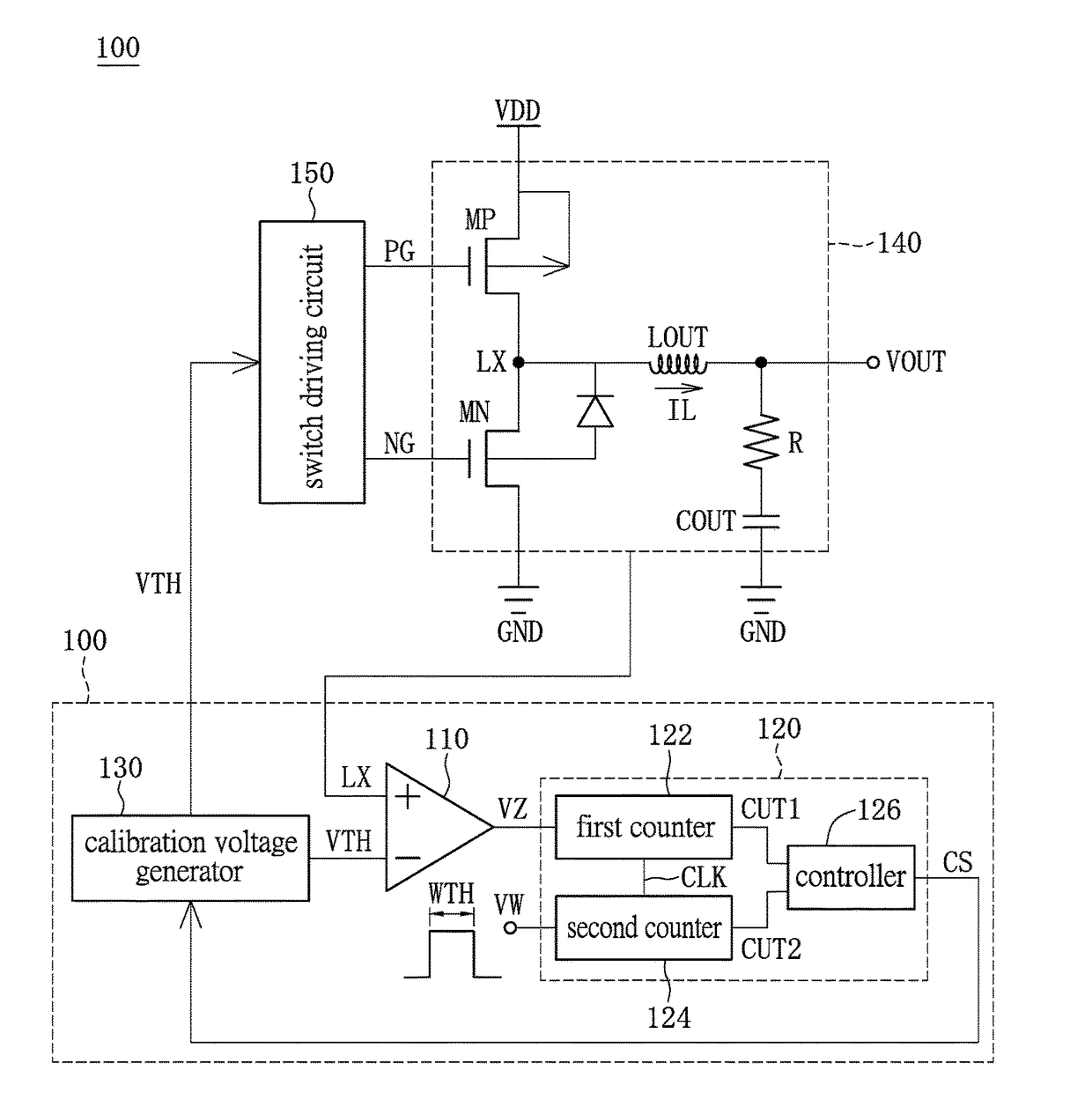
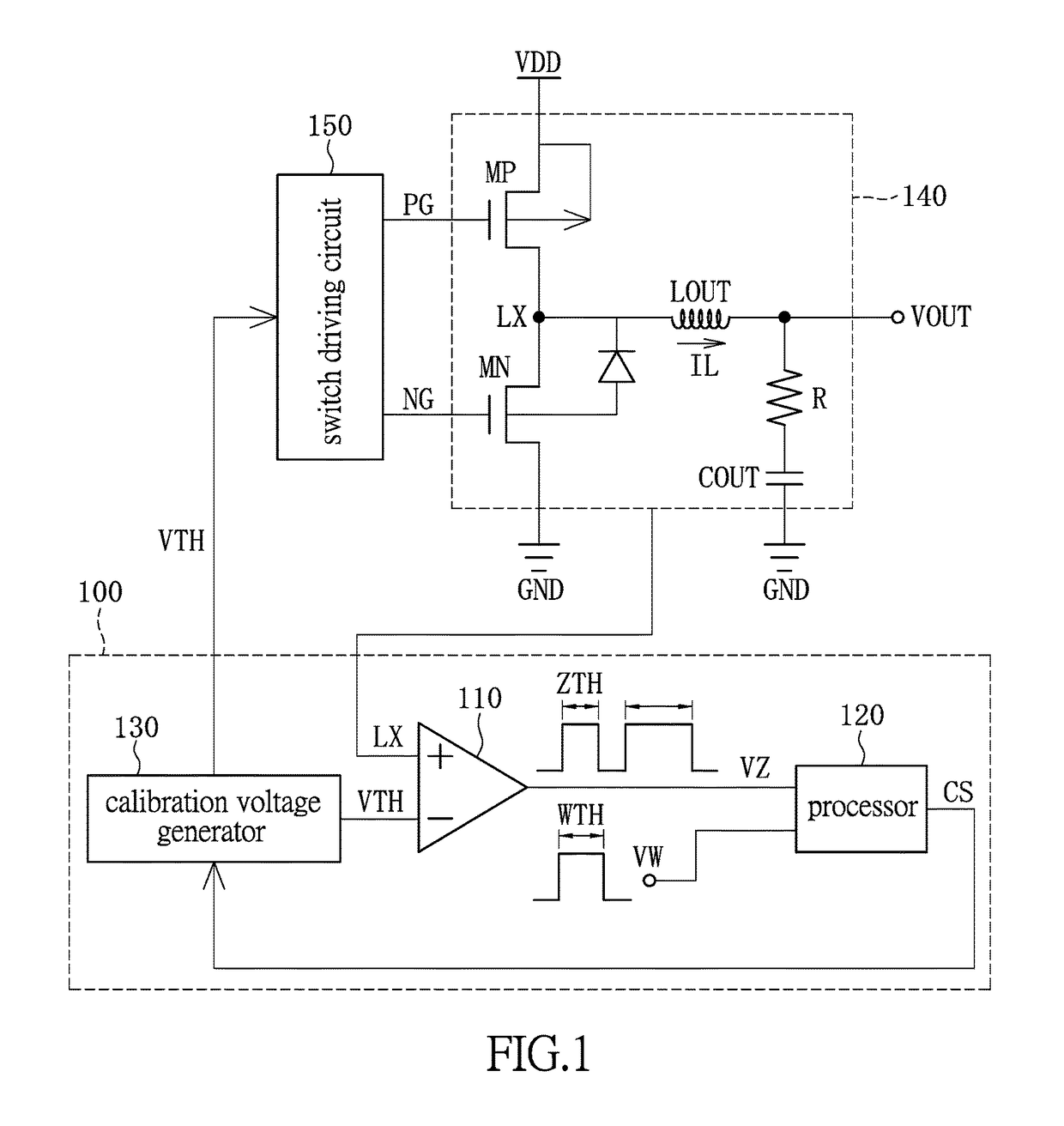
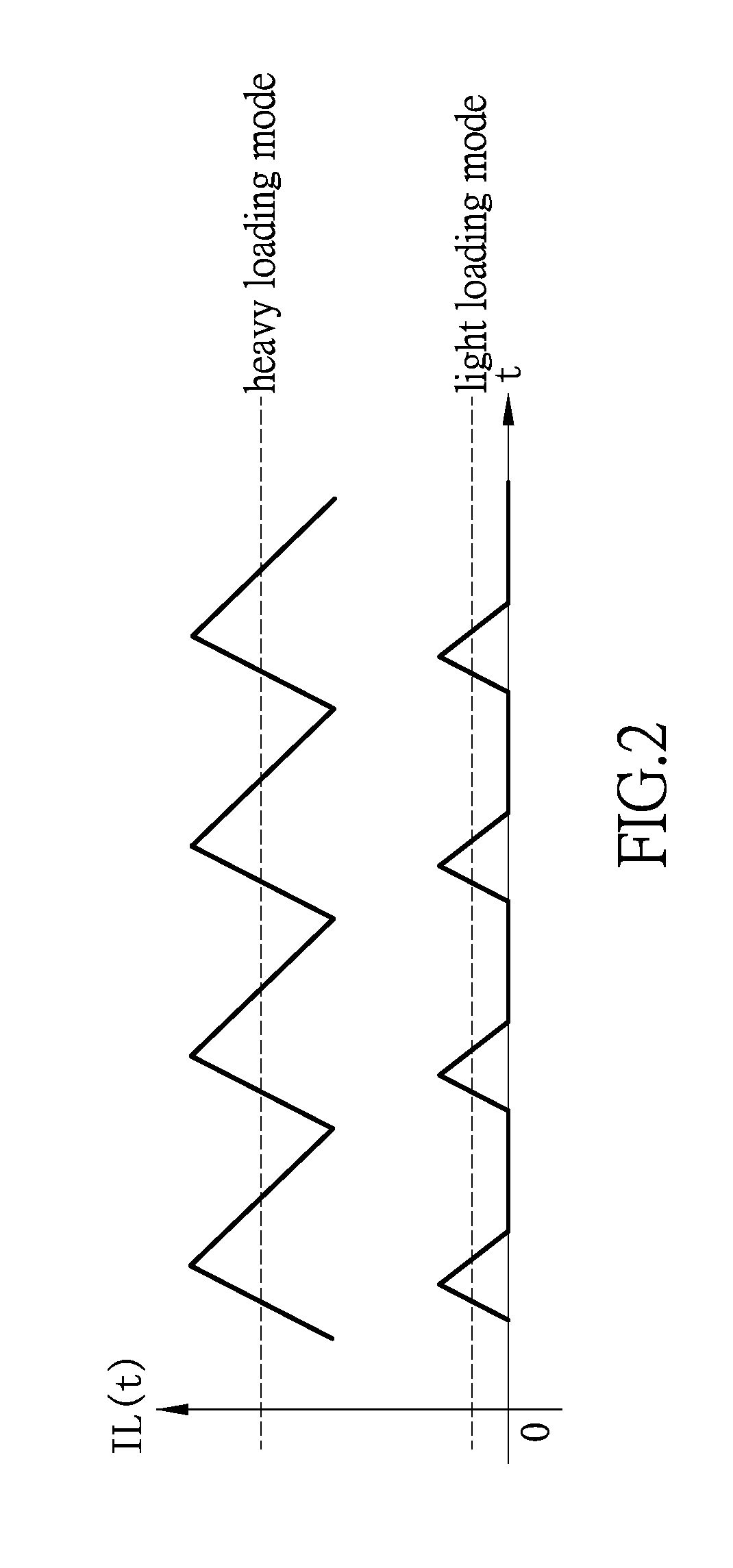
[0018]In conjunction with FIG. 1 and FIG. 2, FIG. 1 shows a block diagram of a feedback control circuit of one embodiment of the instant disclosure, and FIG. 2 shows a waveform diagram of the inductive current of one embodiment of the instant disclosure. As shown in FIG. 1, the feedback control circuit 100 comprises a voltage comparator 110, a processor 120 and a calibration voltage generator 130. The feedback control circuit 100 adjusts the timing when to turn on or off switches in the switching regulating circuit 140. In addition, the switch regulating circuit 140 is electrically connected to a switch driving circuit 150. The non-...


PUM


Abstract

Disclosed are a feedback control circuit and a method thereof. The feedback control circuit includes a voltage comparator, a calibration voltage generator and processor. The voltage comparator receives a middle-point voltage and a calibration voltage, compares the middle-point voltage and calibration voltage, and outputs a reference voltage pulse signal. The calibration voltage generator generates the calibration voltage and outputs it to a switch driving circuit and the voltage comparator. The processor compares the pulse widths of the reference voltage pulse signal and a predetermined voltage pulse signal, and accordingly outputs a control signal to the calibration voltage generator to fine tune the calibration voltage. The switch driving circuit outputs a switch driving signal to a switching regulating circuit to adjust the timing when to turn on or off switches in the switching regulating circuit.

Description

BACKGROUND OF THE INVENTION[0001]1. Field of the Invention[0002]The instant disclosure relates to a feedback control circuit; in particular, to a feedback control circuit that can automatically adjust the timing for turning on or off switches in a switching regulating circuit.[0003]2. Description of Related Art[0004]Usually, in order to improve the efficiency of a switch regulator when it works in the light loading mode, a lower-bridge switch of the switch regulator will be turned off when the inductive current decreases to zero, such that the switch regulator will be in a Discontinuous Conduction Mode (DCM). Commonly, a comparator is used to determine whether the inductive current decreases to zero. However, it is often hard to precisely determine the timing when the inductive current decreases to zero because of an offset voltage of the comparator. As a result, a lower-bridge switch of the switch regulator may be turned off before or after the inductive current decreases to zero, ...

Claims


Application Information

Patent Timeline
Patent Type & Authority Patents(United States)
IPC IPC(8): G05F1/00H02M3/158H02M1/00
CPCH02M3/158H02M1/00H02M2001/0025H02M3/156Y02B70/10H02M1/0025H02M1/0032
Inventor CHEN, SHIH-CHIEHLIN, CHIH-CHENG
Owner REALTEK SEMICON CORP
Why Eureka
Try Eureka