Device for locking rod member using lock block

a technology of locking rod and locking rod, which is applied in the direction of rod connection, mechanical control device, instruments, etc., can solve the problems of difficult assembly, complex configuration, and difficult for even a skilled person to accurately and quickly assemble the respective elements, and achieves simple configuration and easy assembly and disassembly.

Active Publication Date: 2017-09-19
KOREA PNEUMATIC SYST CO LTD
View PDF18 Cites 3 Cited by
  • Summary
  • Abstract
  • Description
  • Claims
  • Application Information

AI Technical Summary

Benefits of technology

[0029]Accordingly, the present invention has been made keeping in mind the above problems occurring in the related art, and an object of the present invention is to provide a device for locking a rod member, having a lock block together with a wedge-type mechanism, thereby providing a simple configuration while enabling easy assembly and disassembly.
[0039]According to the present invention, the locking elements including the outer ring, the inner ring, the pressurizing member, and the spring are integrated and modulated into a lock block, so that they can be assembled and disassembled at one time. Thus, the device of the present invention has a simple structure and is easily assembled and disassembled, compared to that of the related art.

Problems solved by technology

However, there is a problem in that the rod member 14 is still in a movable state when the object has been lifted.
However, it also has problems primarily in that: due to its sliding mechanism,
However, this mechanism also has problems in that it has a complicated structure, so proper arrangement and assembly of respective elements are difficult.
(1) the configuration is complicated;
(2) it is very difficult even for a skilled person to accurately and quickly assemble the respective elements 33 to 38 within a defined space of the housing 32; and
(3) even upon disassembly, treatment of respective elements 33 to 38 is very troublesome and inconvenient.
Thus, locking operation is not stably performed due to such complicated configurations.

Method used


Image

  • Device for locking rod member using lock block
  • Device for locking rod member using lock block
  • Device for locking rod member using lock block

Examples


Embodiment Construction

[0052]These and other features and effects of a device for locking a rod member (also referred to as a ‘locking device’) will be apparent from the description of embodiments with reference to the accompanying drawings. In respective embodiments, like numbers refer to functionally identical elements.

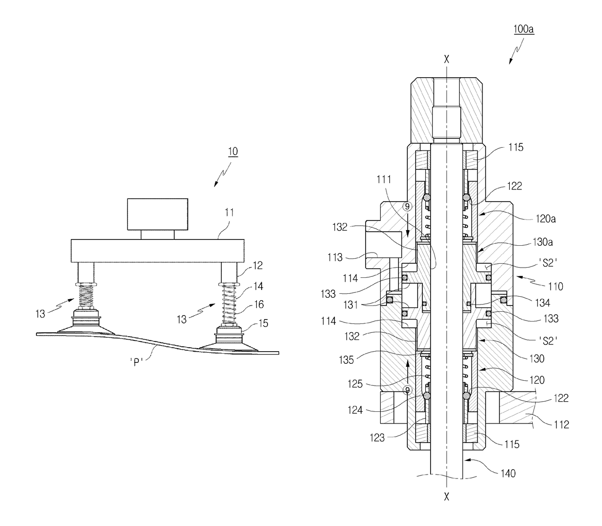
[0053]Referring to FIG. 4, the locking device is denoted as 100. The locking device 100 includes a body section 110 having a vertical hole 111 therein, and a ring-type lock block 120 and a piston 130 serially arranged in the hole 111, wherein a rod member 140 is disposed in the hole to be axially (X-Y) movable through the lock block 120 and the piston 130.

[0054]The above-mentioned elements 110, 120, 130, and 140 will be described in detail with reference to FIGS. 4 to 7.

[0055]The body section 110 having the central vertical through-hole 111 is connected to a robot system via a bracket 112 or a holder. The body section 110 has a fluid passage 113 that passes through an outer wall thereof t...


PUM


Abstract

A device for locking a rod member is provided. The device includes a body section having a vertical hole therein, and a ring-type locking unit and a piston serially arranged along the hole, wherein the rod member is disposed in the hole to be axially movable through the locking unit and the piston. The locking unit may be a lock block including an outer ring having an inclined surface on one side thereof, thereby defining a wedge-type space, an inner ring coaxially disposed in one side of the outer ring and accommodating a pressurizing member interacting with the inclined surface, and a spring disposed in the other side of the outer ring so as to elastically connect the outer ring and the inner ring.

Description

BACKGROUND OF THE INVENTION[0001]Field of the Invention[0002]The present invention generally relates to a device for releasably locking an axially movable rod member.[0003]Description of the Related Art[0004]FIG. 1 shows a suction device that is adapted to a conventional vacuum transfer system. The suction device 10 includes a plurality of level compensators 13 connected to a vacuum chamber 11, wherein the level compensator 13 includes a pipe-type rod member 14, one end of which is inserted into a connection part 12, a suction pad 15 coupled to the other end of the rod member 14, and a spring 16 coaxially disposed around the rod member 14 and connected between the connection part 12 and the suction pad 15.[0005]In this configuration, the rod member 14 is axially movable so that respective suction pads 15 can be brought into close contact with the surface of an object P in a high degree even when the surface is generally uneven. However, there is a problem in that the rod member 14 i...

Claims


Application Information

Patent Timeline
Patent Type & Authority Patents(United States)
IPC IPC(8): F15B15/26G05G5/22F16B7/14F04F99/00F16B47/00
CPCF15B15/262F04F99/00F15B15/26F16B7/149F16B7/1409F16B7/1418F16B7/1463G05G5/22F15B2015/268F15B2211/72F16B47/00G05G2700/08
Inventor CHO, HO-YOUNG
Owner KOREA PNEUMATIC SYST CO LTD
Why Eureka
Try Eureka