
Electric motor
A technology of motors and rotors, applied in the field of motors, can solve the problems of complicated motor control, reversal of size relationship, inability to control phase difference, etc.
Patent Information
- Authority / Receiving Office
- CN · China
- Patent Type
- Applications(China)
- Current Assignee / Owner
- Publication Date
- 2009-01-07
- Estimated Expiration
- Not applicable · inactive patent
Smart Images
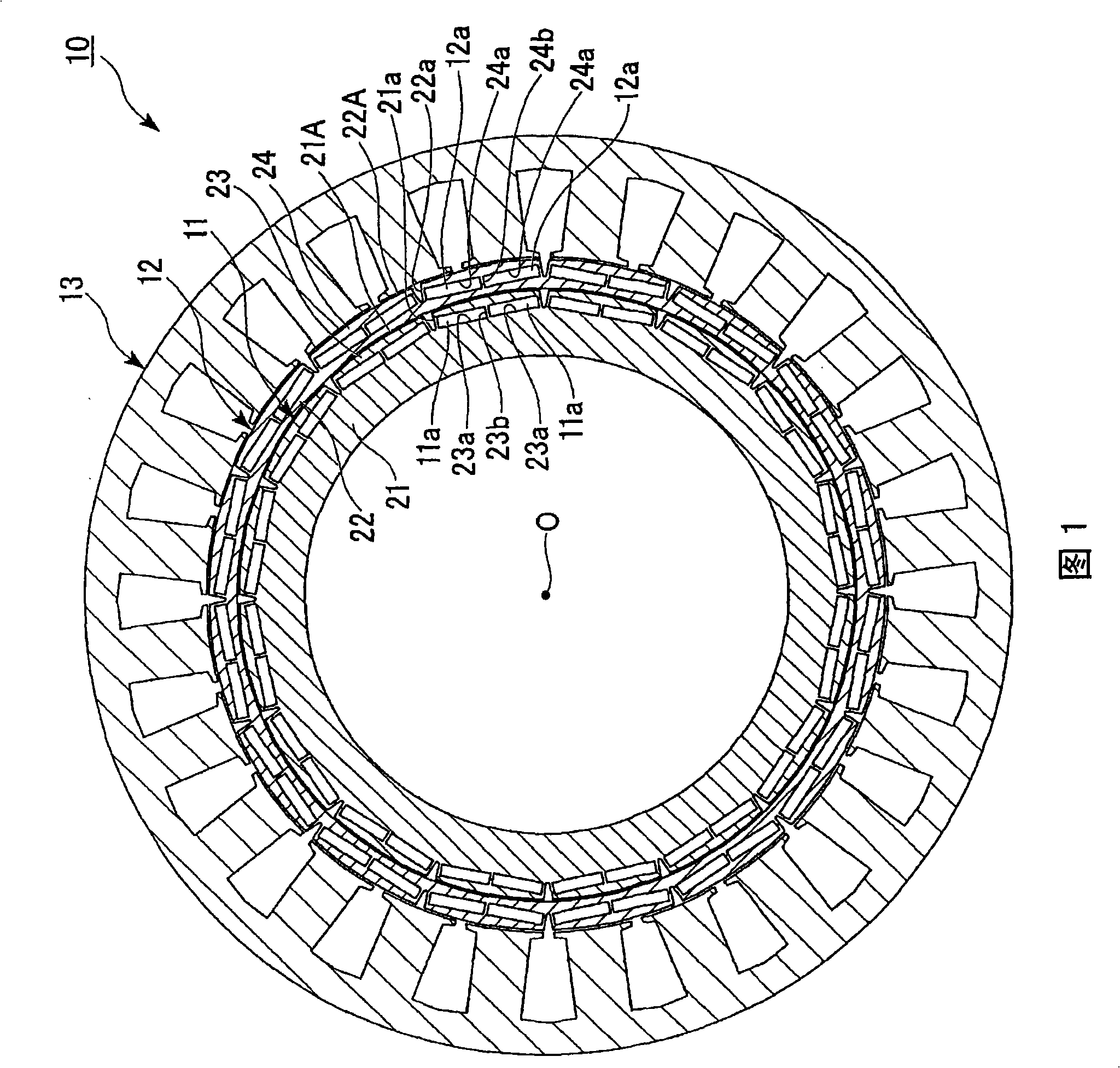
Figure 1 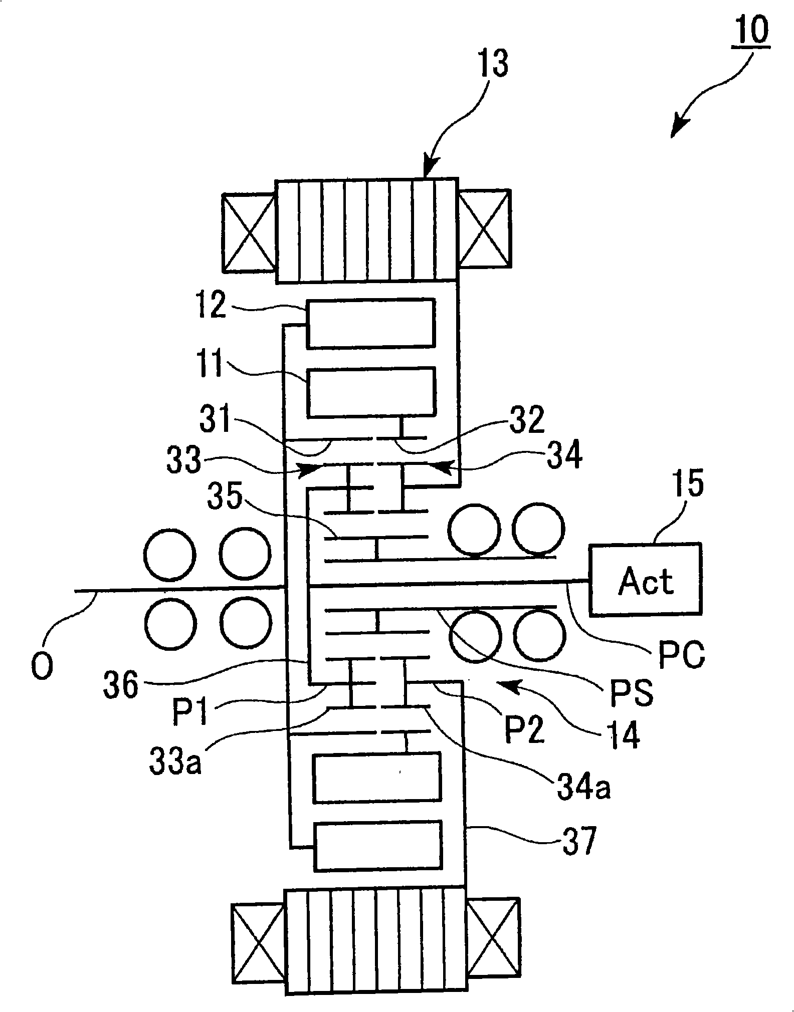
Figure 2 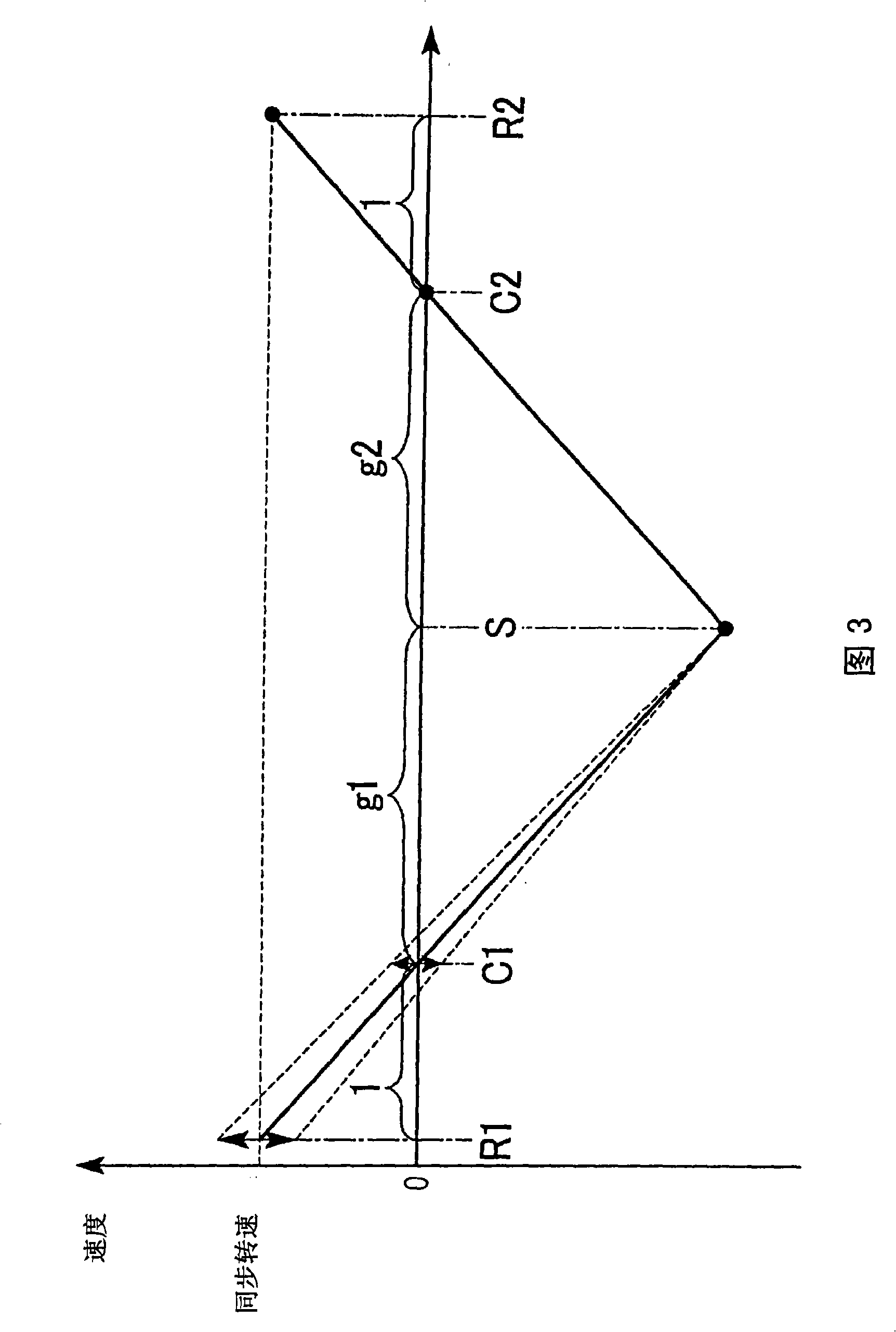
Figure 3
Abstract
Description
technical field
[0001] The present invention relates to electric motors.
[0002] this application claims priority based on Japanese Patent Application No. 2005-367451 for which it applied in Japan on December 21, 2005, and uses the content here. Background technique
[0003] Conventionally, there is known a motor that has, for example, first and second rotors arranged concentrically around the rotation shaft of the motor, and controls the first rotor according to the rotational speed of the motor or the speed of a rotating magnetic field generated by the stator. and the relative position in the circumferential direction of the second rotor, that is, the phase difference (for example, refer to Patent Document 1).
[0004] In this motor, for example, when the phase difference between the first and second rotors is controlled according to the rotational speed of the motor, the relative positions of the first and second rotors in the circumferential direction are changed by a ...
Examples
Embodiment Construction
[0118] Next, an embodiment of a motor according to the present invention will be described with reference to the drawings.
[0119] The motor 10 of the present embodiment is, for example, as shown in FIG. 1 , a brushless DC motor including substantially annular inner-circumferential rotors 11 and outer-circumferential rotors 11 provided with permanent magnets 11a and 12a arranged in the circumferential direction. rotor 12; a stator 13 having a plurality of phases of stator windings 13a that generate a rotating magnetic field that rotates the inner rotor 11 and the outer rotor 12; a planetary gear mechanism 14 that connects the inner rotor 11 and the outer rotor 12; The actuator 15 for setting the relative phase between the inner rotor 11 and the outer rotor 12 through the planetary gear mechanism 14 is mounted on a vehicle such as a hybrid vehicle or an electric vehicle as a drive source. An output shaft P of the electric motor 10 is connected to an input shaft of a transmissi...