
Photoelectrocatalysis water electrolysis method, device and application thereof
A technology for photoelectric catalysis and electrolysis of water, applied in the field of light radiation applications, can solve the problems of high energy consumption, high cost, and difficulty in popularization, and achieve the effects of improving energy efficiency, improving corrosion resistance, and improving power absorption
Patent Information
- Authority / Receiving Office
- CN · China
- Patent Type
- Patents(China)
- Current Assignee / Owner
- Publication Date
- 2012-09-19
- Estimated Expiration
- Not applicable · inactive patent
Smart Images
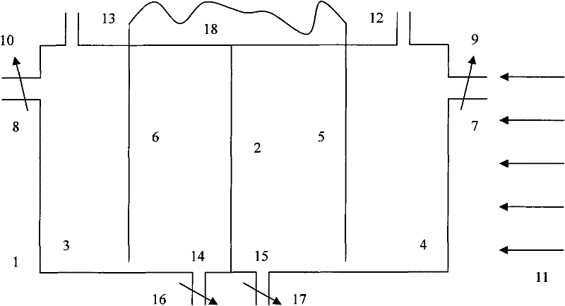
Figure 1 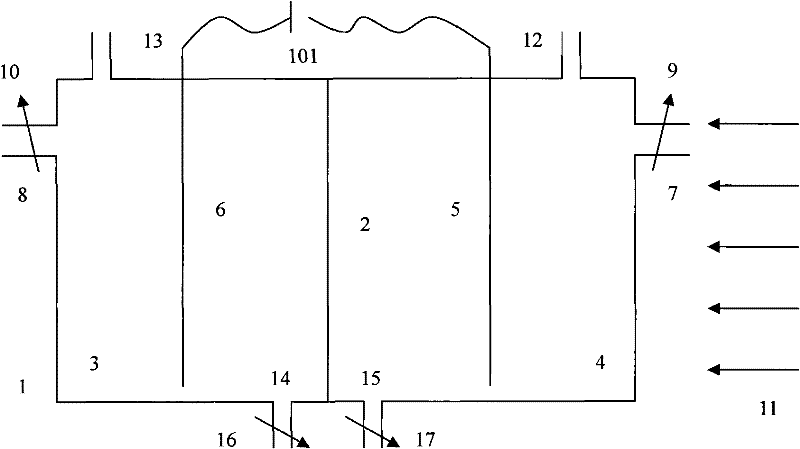
Figure 2 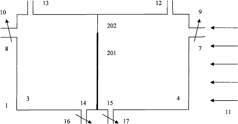
Figure 3
Abstract
Description
technical field
[0001] The invention specifically relates to a photoelectric catalytic water electrolysis method and device capable of electrolyzing water with high efficiency and energy saving to generate weakly alkaline water and acidic water and an application thereof. The weakly alkaline water can be drunk, restore free radicals in the body, balance the acidic constitution of modern people, and contribute to human health; the acidic water can be used to wash vegetables, fruits or tableware, play a role in disinfection and sterilization, and can also be used as Used in lotion, it can disinfect and sterilize and astringe the skin. It belongs to the application field of light radiation. Background technique
[0002] The latest international health standards for drinking water include: (1) no physical, chemical and biological pollution harmful to human health; (2) appropriate amount of minerals (potassium, The content of magnesium, calcium, etc. is 100mg / L); (3) the molecu...
Examples
Embodiment 1
[0048] like figure 1 The schematic diagram of the production principle of the photocatalytic water electrolysis method of the present invention is shown. It can be seen that the photoelectrocatalytic water electrolysis device of the present invention consists of the following parts. A partition 2 is set in the electrolytic water reactor 1, and the electrolytic water reactor 1 is divided into a photoanode chamber 3 and a photocathode chamber 4, and catalytic materials are respectively placed in the photoanode chamber 3 and the photocathode chamber 4 and have a micro-nano structure Photoanode electrode 5 and photocathode electrode 6 (electrode shape can be various shapes: as typical flake or cylinder etc.), supply raw water from water inlet 7 and 8 to photoanode chamber 3 and photocathode chamber 4 respectively ( tap water or drinking water), the flow regulator 9,10 controls the raw water flow rate of the water inlet 7 and 8 respectively, and the sunlight 11 is irradiated from ...
Embodiment 2
[0050] like figure 2 Shown is a schematic structural diagram of Embodiment 2 of the photoelectrocatalytic water electrolysis device of the present invention. in the figure 1 On the basis of the shown preferred embodiment (embodiment one) (the same parts adopt the same mark), a DC power supply 101 is set on the photoanode electrode 5 and the photocathode electrode 6, the positive pole of the power supply is connected to the photoanode, and the negative pole is connected to the photoanode. Photocathode, the voltage is below 50V. This power supply can be household 220V alternating current through transformer rectification, or dry battery or accumulator, or solar cell, other components and the best embodiment with effect, so no more details. By applying a bias voltage to the two electrodes, the separation speed of the electron holes of the catalytic material is increased, so as to further improve the energy efficiency of the photoelectrolysis of raw water.
Embodiment 3
[0052] like image 3 Shown is a schematic structural diagram of Embodiment 3 of the photoelectrocatalytic water electrolysis device of the present invention. in the figure 1 On the basis of the preferred embodiment shown (the same components are marked with the same), a combination of a composite electrode 201 (that is, a photoanode electrode and a photocathode electrode are integrated and deposited on a conductive substrate) and an ion exchange membrane 202 is used to replace the separator 2, other parts and effects are the same as the best embodiment, so no more details.