
Novel V-type diaphragm valve
A diaphragm valve, a new type of technology, applied in the field of valve structure, can solve the problems of high manufacturing cost, heavy overall quality, poor anti-corrosion performance, etc., and achieve the effect of low manufacturing cost, light weight and good anti-corrosion performance
Patent Information
- Authority / Receiving Office
- CN · China
- Current Assignee / Owner
- Publication Date
- 2016-04-13
- Estimated Expiration
- Not applicable · inactive patent
Smart Images
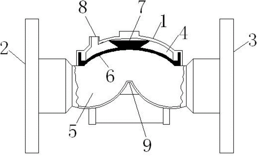
Figure 1 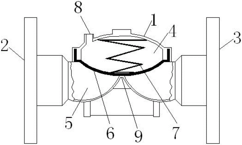
Figure 2
Abstract
Description
technical field
[0001] The invention relates to a valve structure, in particular to a diaphragm valve structure. Background technique
[0002] Conventional V-type diaphragm valve: the valve body is made of cast iron, cast steel, and stainless steel; there are valve shafts and seals on the water passage. It has the problems of heavy overall mass, high manufacturing cost, complex structure, poor anti-corrosion performance, etc., and has a large amount of daily maintenance and low reliability. Contents of the invention
[0003] Purpose of the invention: The purpose of the invention is to overcome the deficiencies in the prior art and provide a new V-type diaphragm valve with simple structure, good anti-corrosion performance, stable and reliable operation, low manufacturing cost and less daily maintenance.
[0004] Technical solution: In order to solve the above technical problems, a novel V-shaped diaphragm valve according to the present invention includes a diaphragm valve ...
Examples
Embodiment Construction
[0011] The present invention will be further described below in conjunction with the accompanying drawings and embodiments.
[0012] Such as figure 1 and figure 2 As shown, a novel V-type diaphragm valve according to the present invention includes a diaphragm valve body 1, one end of the diaphragm valve body 1 in the horizontal direction is a water inlet 2, and the other end is a water outlet 3, and the diaphragm valve body 1. The middle part is the control chamber 4, and the water flow channel 5 is located below the control chamber 4. A rubber diaphragm 6 is provided in the control chamber 4, and a spring 7 is provided between the rubber diaphragm 6 and the top of the control chamber 4. A hydraulic or air pressure control port 8 is provided on the upper part of the control chamber 4, a water-proof boss 9 is provided on the inner side of the lower part of the control chamber 4, and both ends of the rubber diaphragm 6 are arranged within the wall thickness of the diaphragm va...