
Hand-held cable continuity test device and system and test method for rail vehicle
A technology for rail vehicles and continuity testing, which is used in measuring devices, measuring electricity, measuring electrical variables, etc., and can solve problems such as large size, low efficiency, and complicated principles and wiring.
Patent Information
- Authority / Receiving Office
- CN · China
- Patent Type
- Applications(China)
- Current Assignee / Owner
- Publication Date
- 2018-04-13
Smart Images
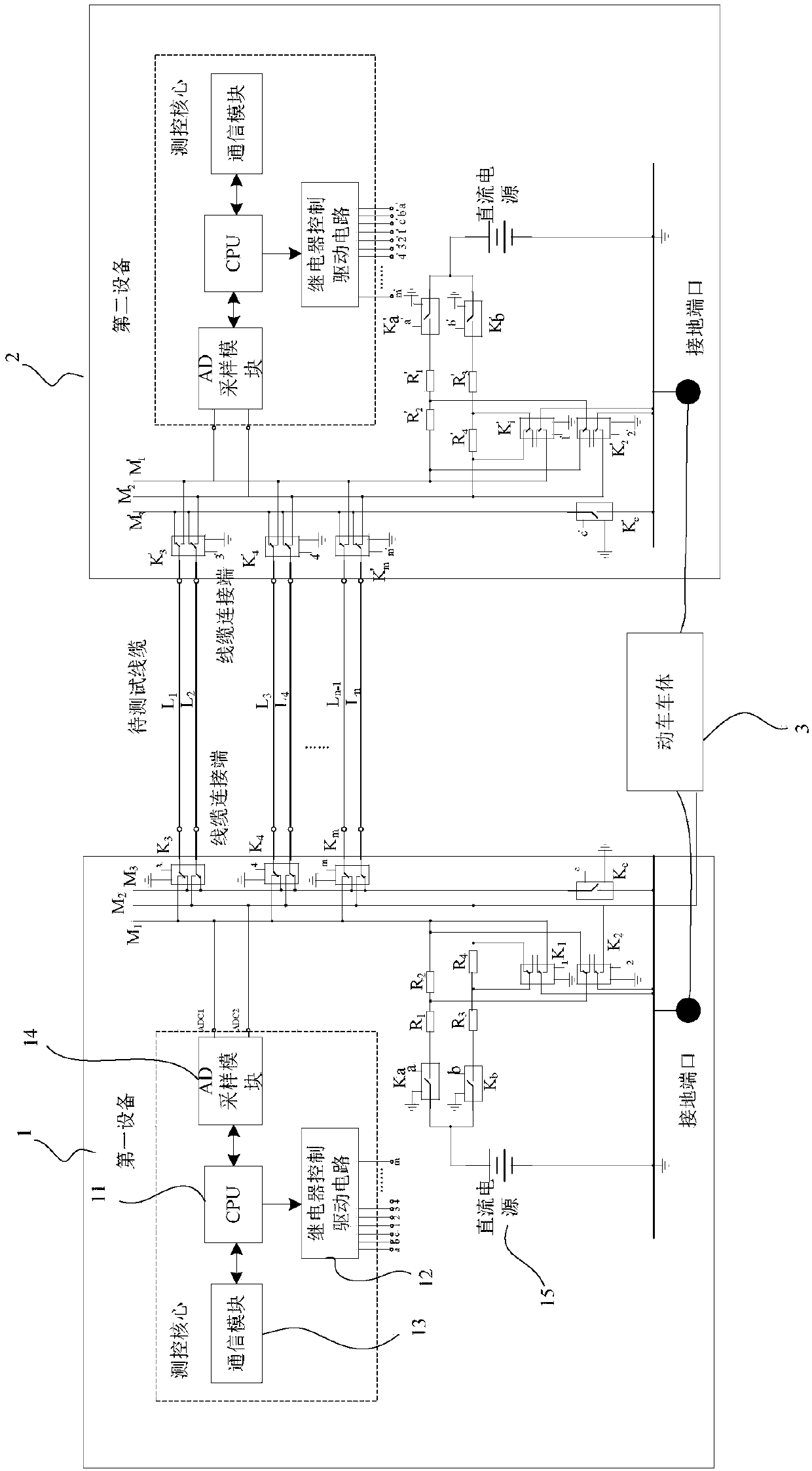
Figure 1 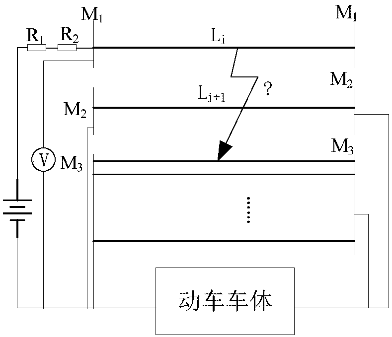
Figure 2 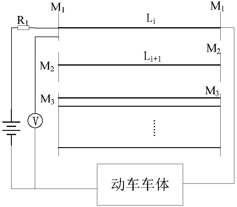
Figure 3
Abstract
Description
technical field
[0001] The invention relates to the field of line testing, and more particularly, to a hand-held cable conduction testing device, system and testing method for rail vehicles. Background technique
[0002] Today, the EMU has become the protagonist of my country's Wanli Railway Line. The cables of the whole vehicle are criss-crossed inside each depot of the EMU, and play a key role in the power operation and communication transmission of the EMU. Their performance directly determines the safety of the EMU operation.
[0003] After the EMU wiring is completed, in order to ensure the reliability of the cable, it is necessary to conduct a continuity test on the cable, including the conduction resistance of the cable and whether there is a short circuit between the lines. The electrical circuit conduction test is the main process of the vehicle circuit test. The circuit conduction test is used to check whether the wiring is correct. It is a very important test ite...
Examples
Embodiment 1
[0079] A hand-held cable conduction test device for a rail vehicle, the rail vehicle includes at least two cables to be tested and a car body, including: at least three busbars, at least one busbar switching module, N grounding switching modules, switching Control the driving circuit and the grounding port used to connect with the vehicle body; N is the number of busbars, and N is a positive integer; the at least three busbars include an idle busbar, and the remaining busbars are test buses;
[0080] The switching control drive circuit is used to send a switching signal;
[0081] Each of the bus switching modules includes an enable input terminal for receiving switching signals, M cable connection terminals and M pairs of switching contacts, two of each pair of switching contacts are respectively connected to the idle bus and one of the The test busbar, the test busbars connected by different switching contacts are different, and the enable input terminal is connected to the M...
Embodiment 2
[0119] The difference from the above embodiment is that the test circuit as the master device also includes M×2 resistors and M resistor switching modules;
[0120] Every two resistors are connected in series in one of the bus power supply circuits, each resistance switching module includes an enable input terminal for receiving a switching signal and a pair of switching contacts, each resistance switching module communicates with each through a pair of switching contacts One resistor in the two bus power supply circuits is connected in parallel to form a resistance parallel circuit, and the enable input terminal of the resistance switching module is connected to the switching contact of the resistance switching module and the switching control drive circuit, for when a switching signal is received, Switching between on and off states of the resistor parallel circuit.
[0121] In this embodiment, when testing the cable short circuit or conduction resistance, the resistance con...