
Rapid analog-to-digital conversion method and analog-to-digital converter
A technology of analog-to-digital converter and analog-to-digital conversion, applied in the direction of analog/digital conversion, code conversion, instruments, etc., can solve the problems of high price, low conversion rate, high speed, etc., and achieve the effect of low cost
Patent Information
- Authority / Receiving Office
- CN · China
- Patent Type
- Applications(China)
- Current Assignee / Owner
- Publication Date
- 2019-03-29
Smart Images
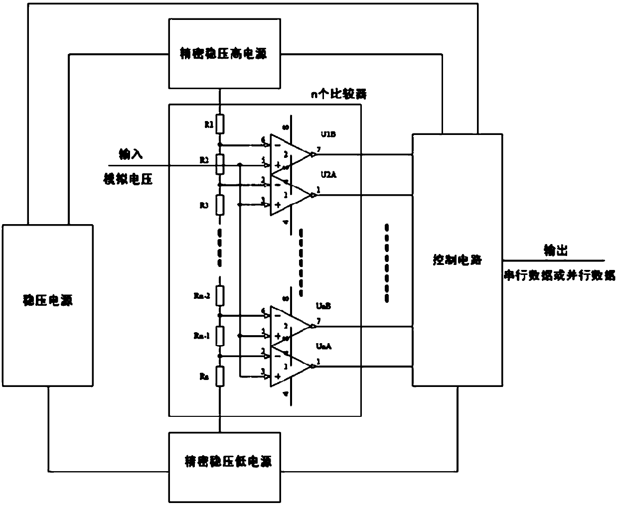
Figure 1 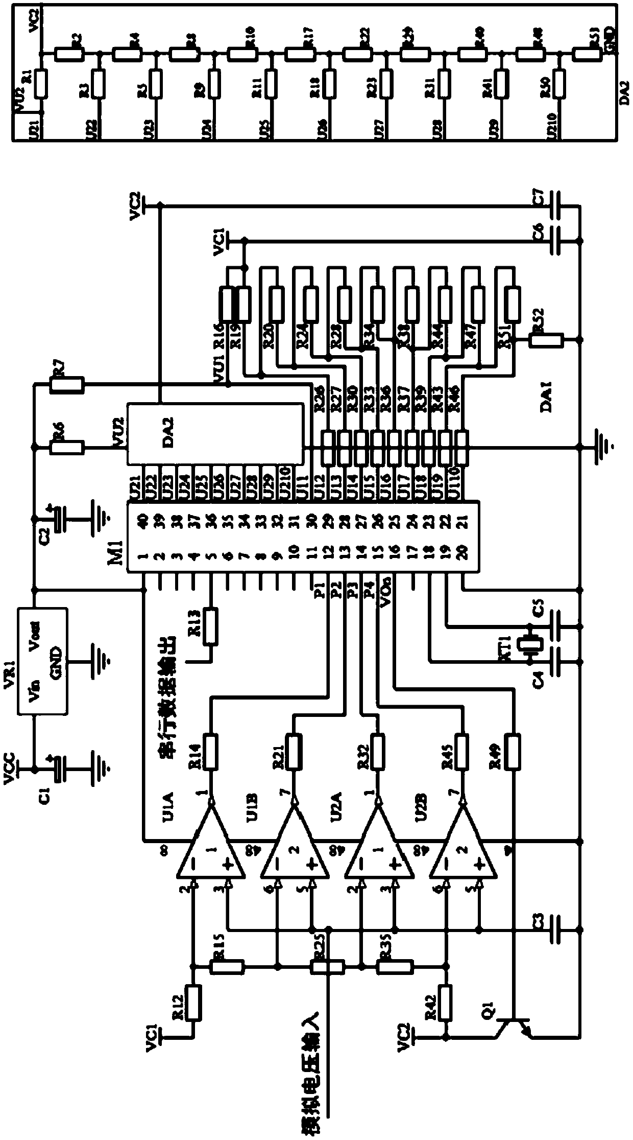
Figure 2 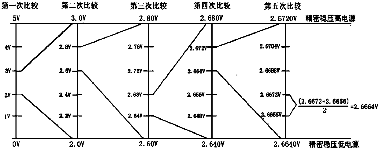
Figure 3
Abstract
Description
technical field
[0001] The invention relates to an analog-to-digital conversion method and an analog-to-digital converter, in particular to a fast analog-to-digital conversion method and an analog-to-digital converter. Background technique
[0002] The existing commonly used several analog-to-digital converters mainly include integral type, successive comparison type, parallel comparison type / serial-parallel comparison type, Σ-Δ modulation type, capacitor array successive comparison type, and voltage-frequency conversion type. The principle and main advantages and disadvantages of the digital converter are as follows:
[0003] (1) The working principle of the integral type AD is to convert the input voltage into time (pulse width signal) or frequency (pulse frequency), and then obtain a digital value by a timer / counter. Its advantage is that high resolution can be obtained with a simple circuit, But the disadvantage is that because the conversion accuracy depends on the int...
Examples
Embodiment Construction
[0030] The present invention will be further described below in conjunction with the accompanying drawings and specific embodiments.
[0031] refer to figure 2 , the present invention provides a fast analog-to-digital converter. The present invention can use 4 to 16 comparators, and this embodiment uses 4 comparators, wherein: resistors R12, R15, R25, R35, and R42 are connected in series to the precision high power supply Between VC1 and precision low power supply VC2, the voltage divider of the string resistors is respectively connected to the negative phase terminals of comparators U1A, U1B, U2A, and U2B, and the positive phase terminals are connected together to be the input terminal of the voltage to be measured, and C3 is the filter capacitor; R14 , R21, R32, R45 are connected to the comparator output to M1; R49 is connected to Q1 for 0V compensation; XT1, C4, C5 are the crystal oscillator circuit of M1; VR1, C1, C2 are connected to the voltage regulator circuit; R7, R16...