
Mobile phone lens cone with protection function
A technology of protective function and protective mechanism, which is applied to equipment with functional cameras, telephone structure, telephone communication, etc., and can solve problems affecting the normal use of mobile phones and increasing the structural area of sliding covers, etc.
Patent Information
- Authority / Receiving Office
- CN · China
- Patent Type
- Applications(China)
- Current Assignee / Owner
- Publication Date
- 2020-02-21
Smart Images
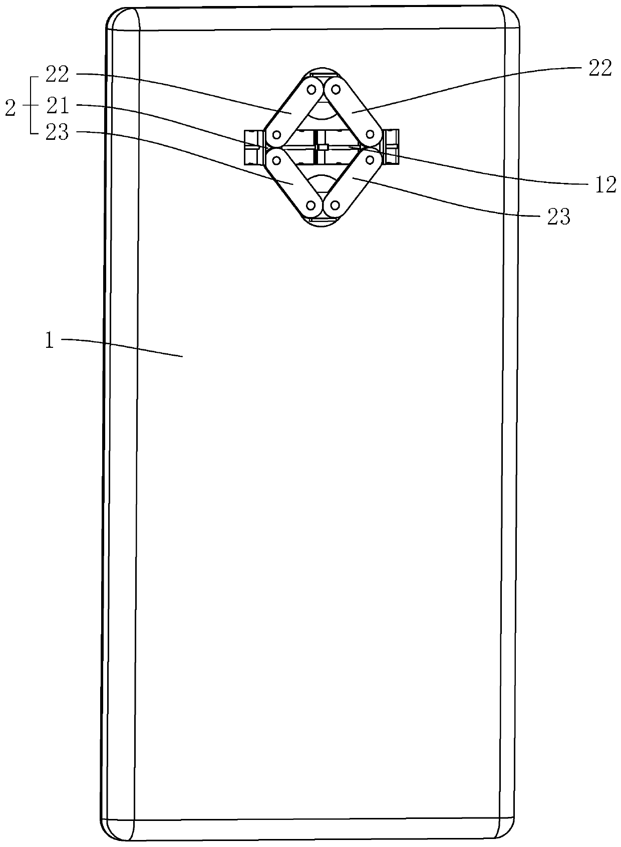
Figure 1 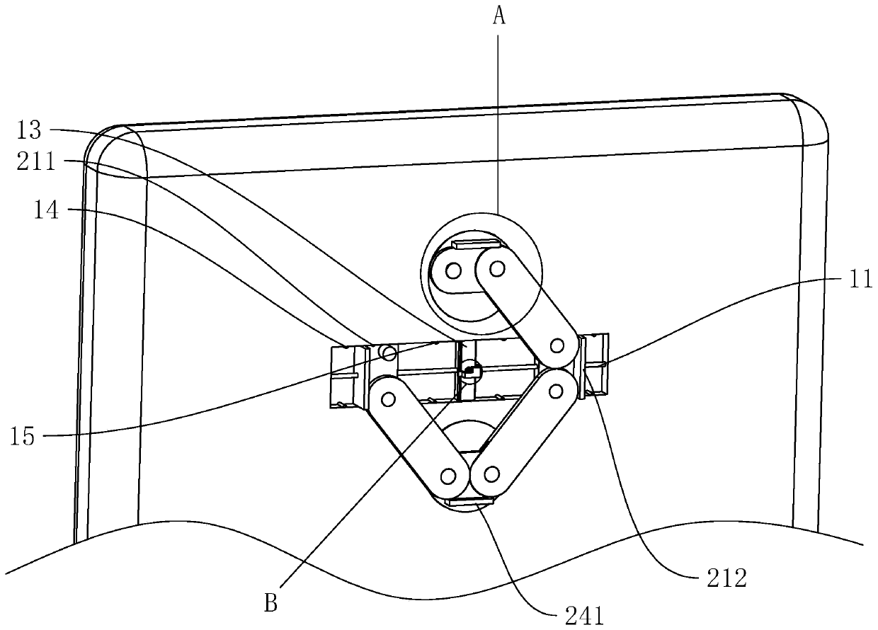
Figure 2 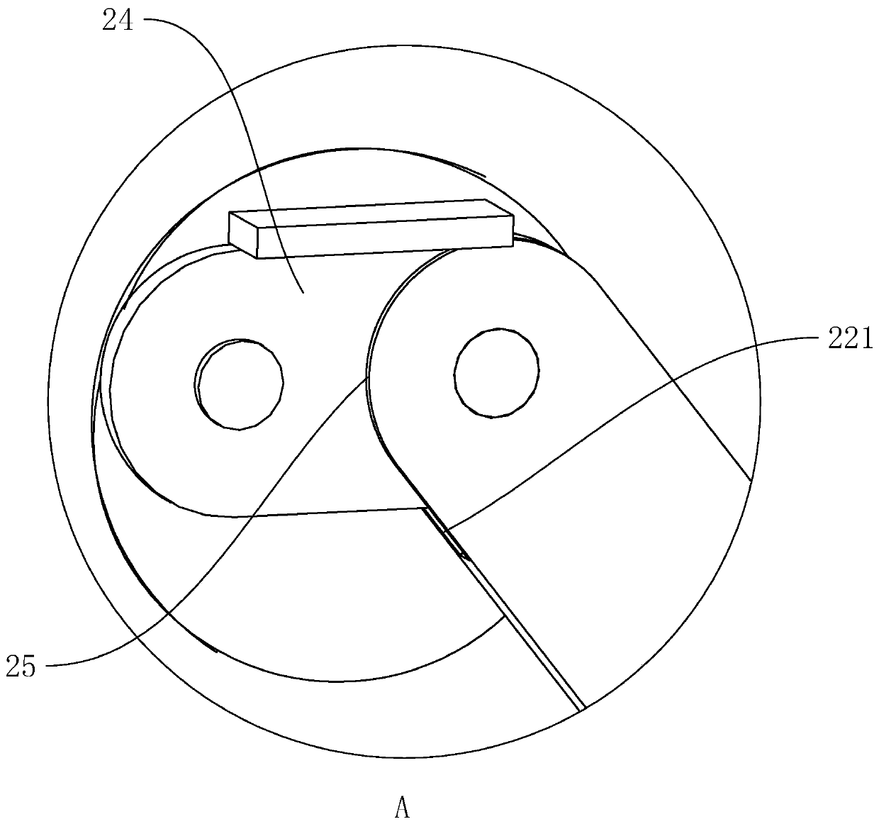
Figure 3
Abstract
Description
technical field
[0001] The invention belongs to mobile phone accessories, and more specifically relates to a mobile phone lens barrel with a protective function. Background technique
[0002] Along with the popularity of mobile phones to ordinary consumers, the cameras of mobile phones are gradually developing towards high-end cameras. In order to protect the cameras, a certain sliding cover structure is usually set for protection.
[0003] In order to increase the shooting effect of existing mobile phones, two cameras are usually arranged on the back of the mobile phone, and the two cameras are vertically arranged. At this time, when the two cameras are protected by a sliding cover structure, the area of the sliding cover structure It needs to be enlarged to protect the two cameras at the same time. At this time, the area of the sliding cover structure will be greatly increased, which will affect the normal use of the mobile phone.
[0004] Therefore need to propose a ...
Examples
Embodiment Construction
[0032] The present invention will be described in further detail below in conjunction with the accompanying drawings.
[0033] A mobile phone lens barrel with protective functions, such as figure 1 As shown, it includes a protection mechanism 2 connected with the body 1 of the mobile phone and used to protect the camera. The protection mechanism 2 includes two rectangular sliding blocks 21 that slide on the back of the body 1, and two blocks that cover the camera above. An upper protective sheet 22 and two lower protective sheets 23 covering the camera below. Between the two cameras of the fuselage 1, there is a sliding groove 11 perpendicular to the connecting line between the centers of the two cameras. A guide rod 12 is adhered in the sliding groove 11, and the two sliding blocks 21 are placed on the slide. Slide in the slot 11, and the guide rod 12 passes through the two sliding blocks 21 at the same time. The two upper protective sheets 22 are all rotatably connected to...