
Distillation type seawater desalination device
A seawater and water collection tank technology, applied in seawater treatment, general water supply conservation, water/sewage treatment, etc., can solve the problems of high maintenance cost, poor quality of desalinated water, and inability to achieve continuous desalination of seawater.
Patent Information
- Authority / Receiving Office
- CN · China
- Current Assignee / Owner
- Publication Date
- 2021-03-09
- Estimated Expiration
- Not applicable · inactive patent
Smart Images
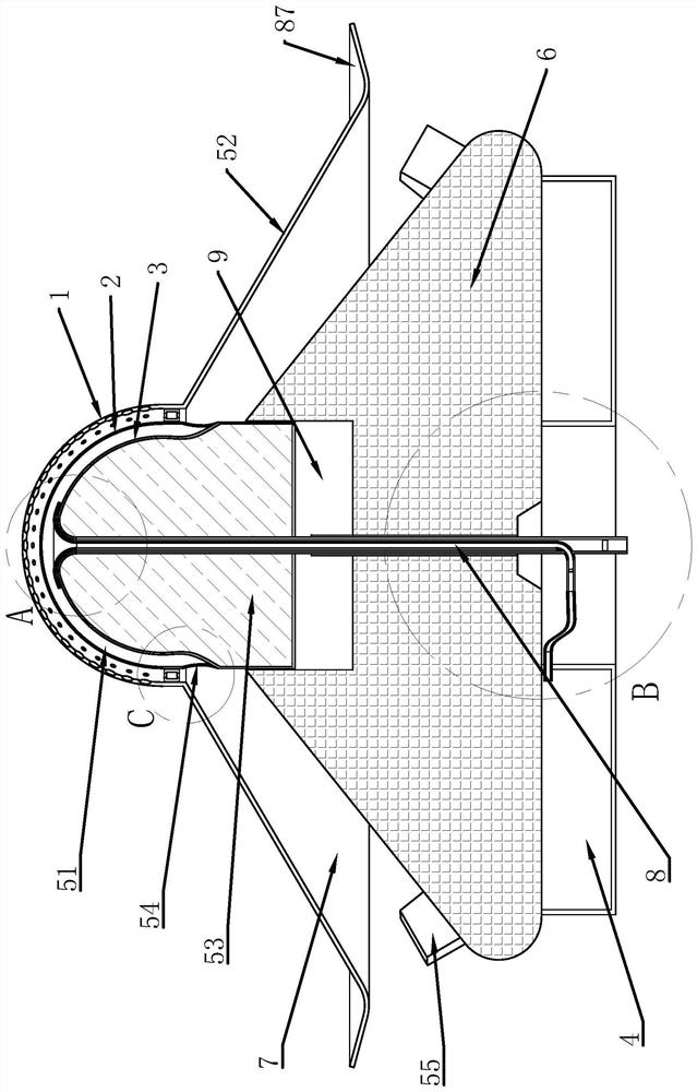
Figure 1 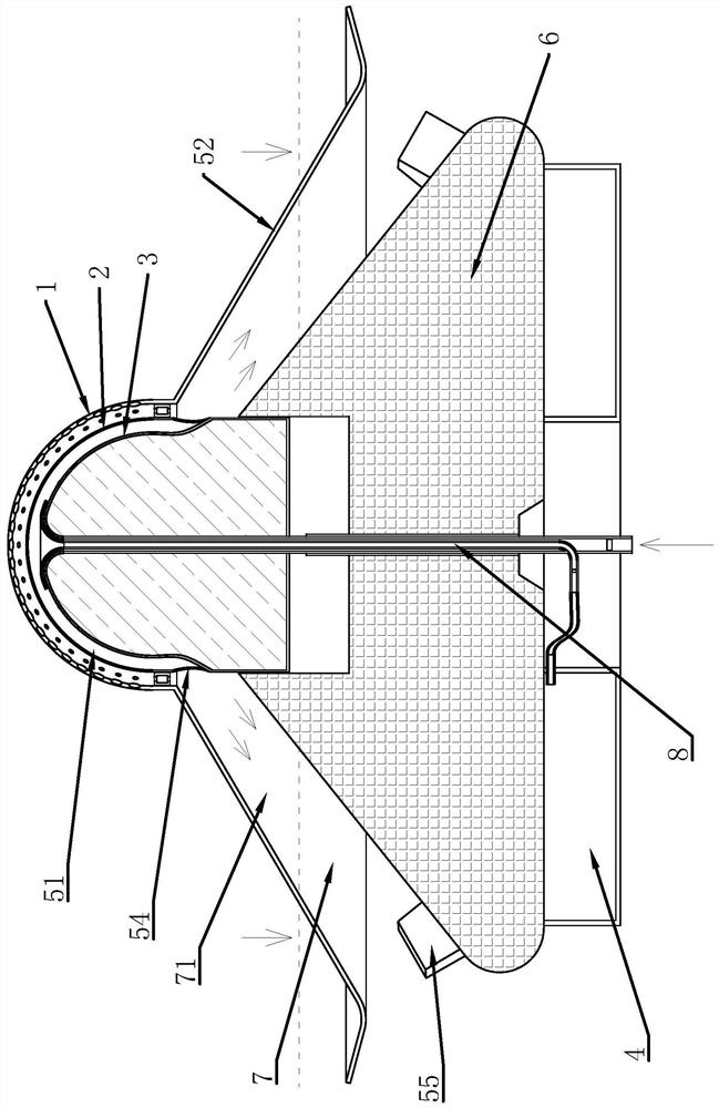
Figure 2 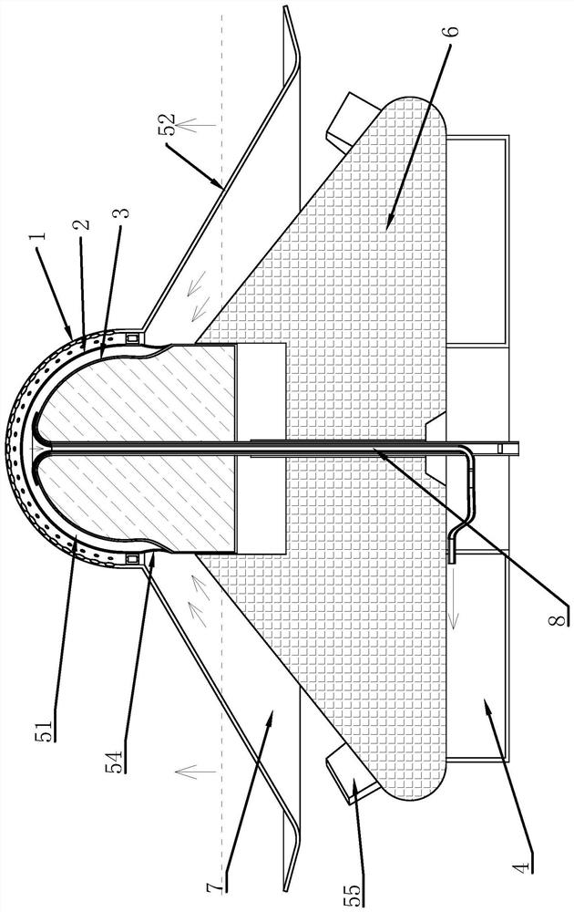
Figure 3
Abstract
Description
technical field
[0001] The invention belongs to the technical field of seawater desalination equipment, and relates to a distillation type seawater desalination device. Background technique
[0002] Seawater desalination equipment is generally divided into distillation type, seawater freezing type, electrodialysis type, reverse osmosis type, and ammonium carbonate ion exchange type. The equipment occupies a large space and the equipment cost is also large.
[0003] The Chinese patent with the patent number [CN200910022145.0] discloses a solar seawater desalination device, which collects sunlight through a convex lens. The seawater is led into the sump, and the sunlight projected on the surface of each convex lens is respectively focused on the seawater liquid surface in the sump. The top of the crown-shaped solar collector is connected to the condensing heat exchanger through a communication tube to evaporate the sump. The water vapor is diverted to the condensing heat exc...
Examples
Embodiment Construction
[0023] The following are specific embodiments of the present invention and in conjunction with the accompanying drawings, the technical solutions of the present invention are further described, but the present invention is not limited to these embodiments.
[0024] Such as figure 1 , Figure 4 , Figure 5 , with 6 and Figure 7 As shown, it includes a heat collecting cover 1, a heat shield 2, a heat receiving cover 3 and a water collection tank 4. The heat shield 2 is located inside the heat collecting cover 1, and the heat receiving cover 3 is located inside the heat shield 2. The heat shield 2 and the heat receiving cover 3 are fixedly connected, a volatilization chamber 51 is formed between the heat shield 2 and the heat receiving cover 3, and a tapered partition cylinder 52 is fixedly connected to the outer edge of the heat collection cover 1, and the partition cylinder 52 is a cone cylinder whose upper end diameter is smaller than the lower end diameter shape, the oute...