
Vertical shaft flood discharge tunnel horizontal section excavation method
A technology for flood discharge tunnels and horizontal sections, which is applied in excavation, shaft equipment, and sinking, etc., which can solve problems such as insufficient safety considerations, reduced construction efficiency, and complex stress, so as to ensure the safety of excavation and ensure the stability of excavation Sexuality and the effect of ensuring construction efficiency
Patent Information
- Authority / Receiving Office
- CN · China
- Patent Type
- Applications(China)
- Current Assignee / Owner
- Publication Date
- 2022-03-25
Smart Images
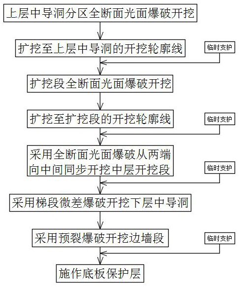
Figure 1 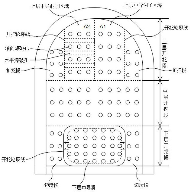
Figure 2
Abstract
Description
technical field
[0001] The invention belongs to the technical field of excavation and construction of a horizontal section of a flood discharge tunnel, and in particular relates to a method for excavating a horizontal section of a vertical shaft flood discharge tunnel. Background technique
[0002] In water conservancy and hydropower projects, flood discharge tunnels are an indispensable structure for rapid drainage and buffering of water flow. The internal water velocity of the spillway tunnel is high, the water flow rate is large, and the stress is complex. Therefore, it is necessary to fully consider the safety of the spillway tunnel construction under the premise of ensuring the construction efficiency during the construction of the spillway tunnel.
[0003] Most of the excavation construction of the horizontal section of the existing flood discharge tunnel directly adopts the method of full-section smooth blasting excavation, that is, the excavation is carried out direc...
Examples
Embodiment 1
[0036] A method for excavating the horizontal section of the shaft flood discharge tunnel in this embodiment, such as figure 1 and figure 2 shown, including the following steps:
[0037] Step 1. Divide the horizontal section of the flood discharge tunnel from top to bottom into an upper excavation section, a middle excavation section, and a lower excavation section;
[0038] The total height of the spillway tunnel is 15.6m, the width is 11.2m, and the excavation section of the lower layer is 0m≤H from the ground 3 For the area ≤2m, the excavation section of the middle layer shall be 2m2 ≤8.1m, the upper excavation section is 8.1m1 ≤15.6m. It should be noted that the upper excavation section includes the top arc of the spillway tunnel and the side walls on both sides.
[0039] Step 2. First excavate the upper middle pilot tunnel in the upper excavation section layer by layer using the full-face smooth surface blasting excavation method, and then expand the excavation sectio...
Embodiment 2
[0045] This embodiment is further optimized on the basis of embodiment 1, such as figure 2 As shown, the step 2 specifically includes:
[0046] Step 2.1. According to the direction of the main stress of the rock mass in the upper middle pilot tunnel, divide the upper middle pilot tunnel to obtain several upper middle pilot tunnel sub-areas, and then excavate the excavation surface of an upper middle pilot tunnel sub-area along the direction parallel to the axis of the spillway tunnel Axial blast holes are drilled upwards and full-section smooth blasting is carried out on the current upper intermediate pilot tunnel sub-area, and then the current upper intermediate pilot tunnel sub-area is excavated to a specified depth;
[0047] As shown in the figure, the main stress direction of the rock mass in the upper middle pilot tunnel is the horizontal direction, so the upper middle pilot tunnel is divided into two upper middle pilot tunnel sub-areas A1 and A2 along the horizontal dir...
Embodiment 3
[0055] This embodiment is further optimized on the basis of the above-mentioned embodiment 1 or 2. In the step 2.2, the axial blast holes and the horizontal blast holes are arranged at staggered intervals, and the axes of the axial blast holes and the horizontal blast holes The distance between the axes is greater than or equal to 40cm. The distance between the axis of adjacent axial blast holes and the axis of horizontal blast holes is greater than or equal to 40cm, and the axial blast holes and horizontal blast holes are arranged at staggered intervals, that is, the axial blast holes and horizontal blast holes cannot be separated. interconnected.
[0056] The distance between the excavation depth of the expansion section in step 2.4 lagging behind the excavation depth of the pilot tunnel in the upper layer is 80cm-100cm.
[0057] The periphery of the axial blast hole in step 2.1 and step 2.2 is provided with a blasting buffer hole, and the periphery of the blasting buffer h...