
Method for processing a workpiece
Patent Information
- Authority / Receiving Office
- US · United States
- Current Assignee / Owner
- Publication Date
- 2020-08-18
Smart Images
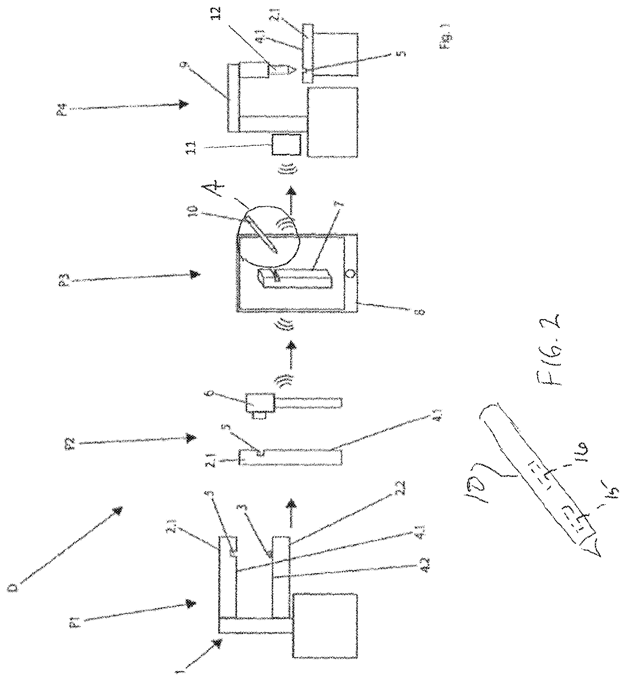
Figure 1 
Figure 2
Abstract
Description
BACKGROUND OF THE INVENTION
[0001] The invention relates to a method for processing a workpiece using a tool, in particular for repairing a surface using a laser, the tool being piloted by a control element.
[0002] Methods of this kind for processing a workpiece using a tool, for example a laser, are known in a great many forms and embodiments. In that context, lasers can be used in many forms for the processing of workpieces, such as for cutting workpieces, hardening workpiece surfaces, or also for connecting workpieces by welding. In this processing method, it is often necessary to observe the workpiece region that is to be processed using an observation device, such as a microscope, in order to be able to guide with sufficient precision over the workpiece a laser beam that is used for processing. If the welding takes the form of deposition welding, in which a welding wire must be brought over the point that is to be welded, the use of such an observation device is practically indispe...
Examples
Embodiment Construction
[0026]Other advantages, features and details of the invention can be found in the following description of preferred exemplary embodiments and in the drawing, which shows, in FIG. 1, a schematic illustration of an apparatus according to the invention for processing a workpiece. This figure represents the schematic illustration D of the process according to the invention, with the process steps P1-P4.
[0027]The preferred exemplary embodiment shows, as first process step P1, a press 1, for example from the automotive industry. This tool has dies 2.1 and 2.2. If an object 3, for example a screw, were now to fall between the dies 2.1 and 2.2, and the dies 2.1 and 2.2 close, at least one surface 4.1 and / or 4.2 of at least one die 2.1 and / or 2.2 would suffer substantial damage, resulting in a flaw 5.
[0028]In order to repair this flaw 5, in a second process step P2 a camera 6, preferably a 3D camera, is moved to the flaw 5. This records a 3D image 7 of the damaged location.
[0029]In order to...