
Adaptive self-centering apparatus and method for seismic and wind protection of structures
a self-centering apparatus and structure technology, applied in the direction of shock absorption devices, shock proofing devices, gearing, etc., can solve the problems of affecting the mental and physical health of the occupants, the buffeting of wind turbulence, and the vibration of vortex-induced vibrations of the structure, so as to increase the restoring force of the device, increase the acceleration, and reduce the effect of mass
Patent Information
- Authority / Receiving Office
- US · United States
- Patent Type
- Patents(United States)
- Current Assignee / Owner
- Publication Date
- 2021-10-05
Smart Images
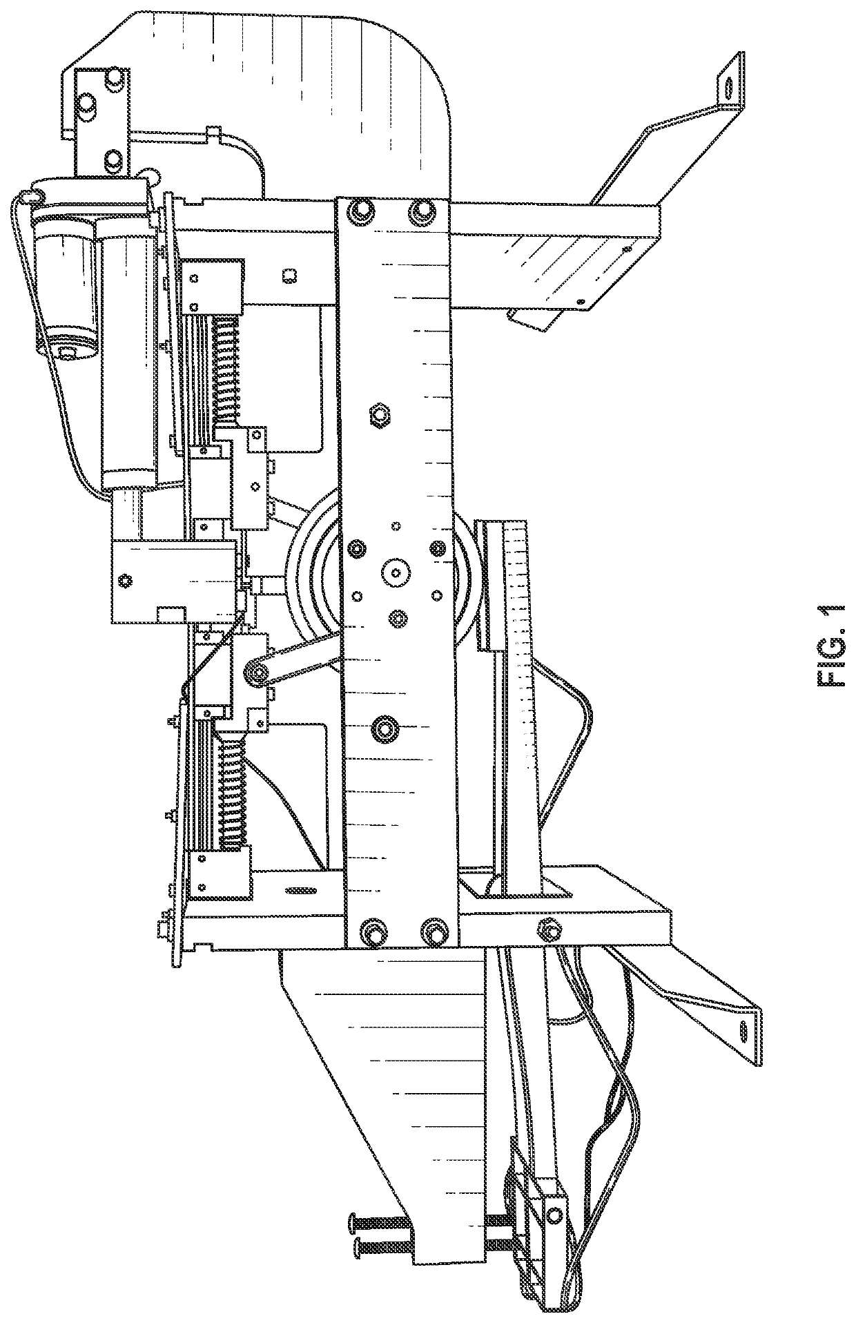
Figure 1 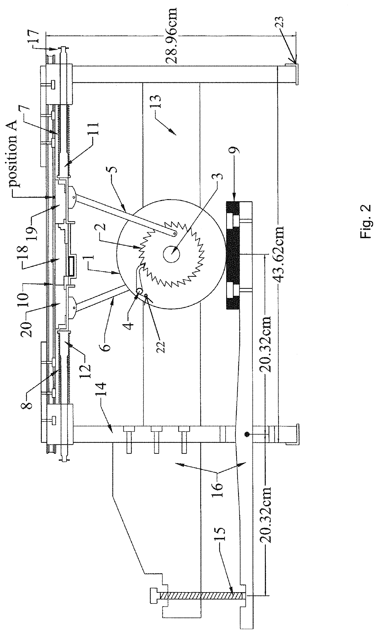
Figure 2 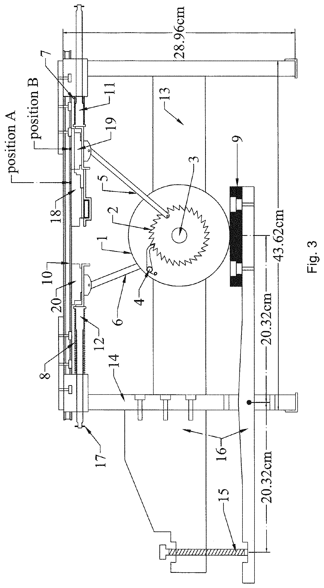
Figure 3
Abstract
Description
CROSS-REFERENCE TO RELATED APPLICATIONS
[0001] This application claims priority to and the benefit of the filing of U.S. Provisional Patent Application No. 62 / 505,489, entitled “Adaptive Self-Centering Apparatus and Method for Seismic Protection of Structures”, filed on May 12, 2017, and the specification thereof is incorporated herein by reference.BACKGROUND OF THE INVENTIONField of the Invention (Technical Field)
[0002] Embodiments of the present invention relate to a new adaptive self-centering device for structural protection using a combination of a friction-ratchet-pawl-lever mechanism. More particularly, embodiments of the present invention relate to an adaptive self-centering apparatus that is couplable to a structure and which dampens movement of the structure.DESCRIPTION OF RELATED ART
[0003] According to the Insurance Information Institute, the average annual loss of insured property from earthquake and tsunami was $2.8 billion globally from 2014 through 2017. Per the Federal E...
Examples
case 1
g: Right Cartridge Moves Towards Right
[0053]Referring now to FIGS. 6 and 7, F is the external lateral force acting towards the right. The component of this force (BD) that is transferred to right lever 5 is Fa. P is the force exerted on friction wheel 1 by pad 9 to produce the breakaway friction force μarP. Although pad 9 is generally referred to as a “rubber pad” such description is merely intended to apprise the reader of the most preferred embodiment and other materials, including but not limited to other elastic or flexible materials, can be used and will provide desirable results. Here μar is the frictional coefficient between friction pad 9 and friction wheel 1 (aluminum on rubber in the most preferred embodiment). Accordingly, in one embodiment, one or more brake pads could also be used. Likewise, although the figures illustrate an embodiment wherein the friction pad is forced upward against an outer edge of the friction wheel, in one embodiment, a pair of friction pads can b...
case 2
ing: Right Cartridge Moves Towards Left
[0064]As best illustrated in FIGS. 8 and 9, when the right cartridge moves from right to left, the ratchet wheel rotates in a clockwise direction. The friction wheel remains static as the pawl ratchets over the ratchet wheel and thus the breakaway friction force between the friction pad and the friction wheel need not be overcome by the active force F.
From the free body diagram of joint B (see FIG. 9),
Fa=F / cos(θ2) (Equation 9)
wherein Fa is the compressive force in the member BD.
From the free body diagram of joint D (see FIG. 9), resolving the force Fa into tangential (Ft) and radial (Fr) components gives
Ft=Fa sin(ω)
Fr=Fa cos(ω) (Equation 10)
wherein Fr generates the friction force (μssFr) between the ratchet wheel and the shaft (steel on steel). μss is the friction between steel on steel.
[0065]The reactive frictional moment Mss (see Equation 3) due to the relative motion between the ratchet wheel and the shaft will act as illustrated in FIG. 9...
example 1
Instrumentational Setup on the ASCD for Experiments
[0084]FIG. 10 illustrates an experimental setup of the device that was constructed wherein center cartridge 18 was connected to actuator 21, which was powered by a 12V DC supply. This cartridge also had tension-compression load cell 23 attached to it, which measured the force applied to cartridge 18 by actuator 21.
[0085]The counterweight force was measured by another set of load cells that were attached to the tip of counterweight screw 15. The tests were carried out in a displacement controlled fashion. Incremental displacements were applied to the actuator manually by using a two-way control regulator. The magnitudes of different parameters of the ASCD, including the friction coefficients, are illustrated in the following table.
[0086]
TABLE 1Parameters of the ASCDSI. No.SymbolMeaningMagnitudeUnit1a|BD|101.60mm.2b|OD|31.753c|EA|58.904RRadius of the friction wheel63.505h|OE|81.536rRadius of the shaft11.817rrMean radius of the ratchet...