
Method for hydroenhancing fabrics using a shaped orifice
a technology of hydro-enhancing fabrics and orifices, which is applied in the direction of drying machines, lighting and heating apparatus, and drying machines with progressive movements. it is not feasible to simply increase the number of orifices per inch, and is difficult to make and maintain multiples
Patent Information
- Authority / Receiving Office
- US · United States
- Patent Type
- Applications(United States)
- Current Assignee / Owner
- Publication Date
- 2003-06-05
- Estimated Expiration
- Not applicable · inactive patent
Smart Images
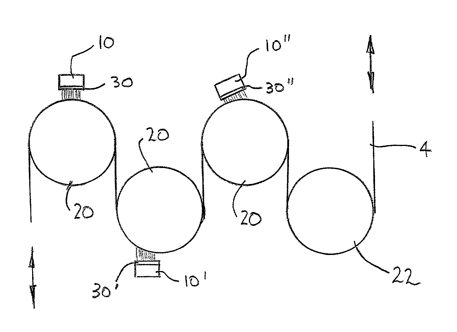
Figure 1 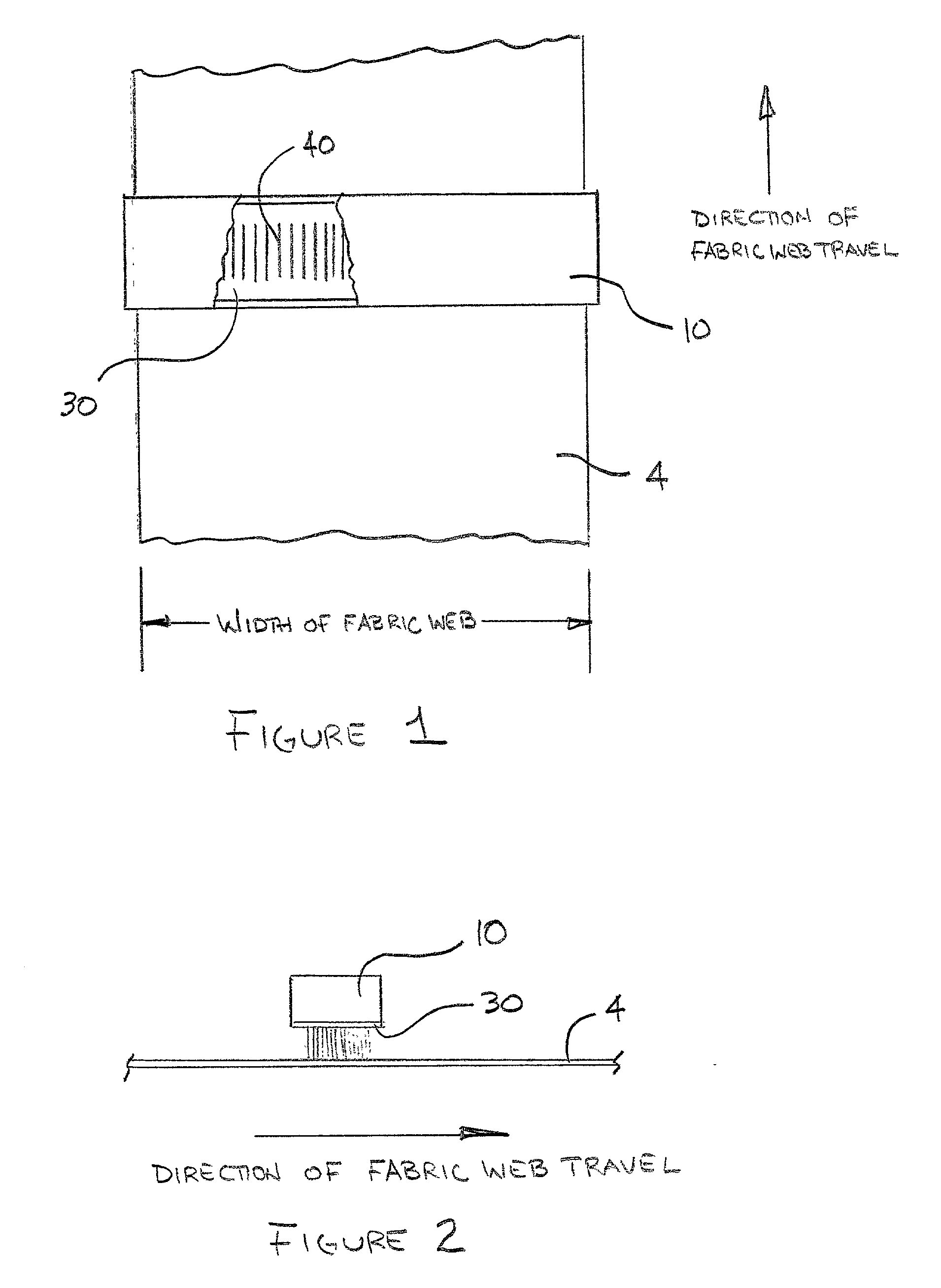
Figure 2 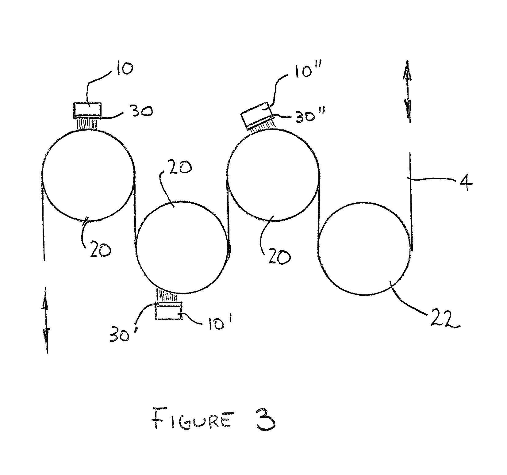
Figure 3
Abstract
Description
BACKGROUND OF THE PRESENT INVENTIONSUMMARY OF THE PRIOR ART
[0001] This invention relates to a method for hydroenhancing fabrics, and more particularly to a method for hydroenhancing fabrics using a shaped orifice wherein a liquid under pressure is forced through a non-circular orifice in a coherent jet and impinges onto a fabric. Multiple orifices are typically used, and the shape and orientation of the orifices (e.g. the distance between adjacent orifices, the angle between the major axes of the orifices and the direction of fabric travel and the direction of impingement) can be modified to effect different hydroenhancement properties. The method of hydroenhancement can be practiced using a variety of machinery configurations. One use for the method of the present invention is to impart "striping," i.e. a selective color wash-out to produce a pattern of alternating lighter and darker stripes across the width, and running the length of a fabric web.
[0002] The impingement of a liquid...
Examples
Embodiment Construction
[0105] FIG. 1 is a plan view of a moving web and a partially cut-away manifold.
[0106] In one embodiment of the present invention, a fabric web 4 passes underneath a manifold 10. Partially shown in the cut-away portion of manifold 10 is the orifice strip 30 and a series of parallel elongated orifices 40 in the orifice strip 30, where the major axes of the elongated orifices 40 are parallel with the direction of travel of fabric web 4. In FIG. 1, manifold 10 is placed so its longitudinal axis is perpendicular to the direction of travel of fabric web 4, and fabric web 4 appears to be on a flat support surface (not shown). However, it is within the practice of the present invention to orient manifold 10 so that its longitudinal axis is not perpendicular to the direction of travel of fabric web 4.
[0107] FIG. 2 is a side elevation view of a moving web, a manifold and an orifice strip.
[0108] In one embodiment of the present invention, moving fabric web 4 passes underneath manifold 10 and o...