
Survey system
a technology of a surveillance system and a detection system, applied in the field of surveillance systems, can solve the problem that the collimation target b>3/b> cannot be properly found
Patent Information
- Authority / Receiving Office
- US · United States
- Patent Type
- Applications(United States)
- Current Assignee / Owner
- Publication Date
- 2005-11-17
- Estimated Expiration
- Not applicable · inactive patent
Smart Images
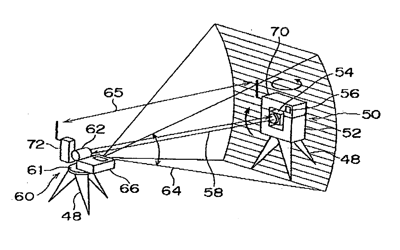
Figure 1 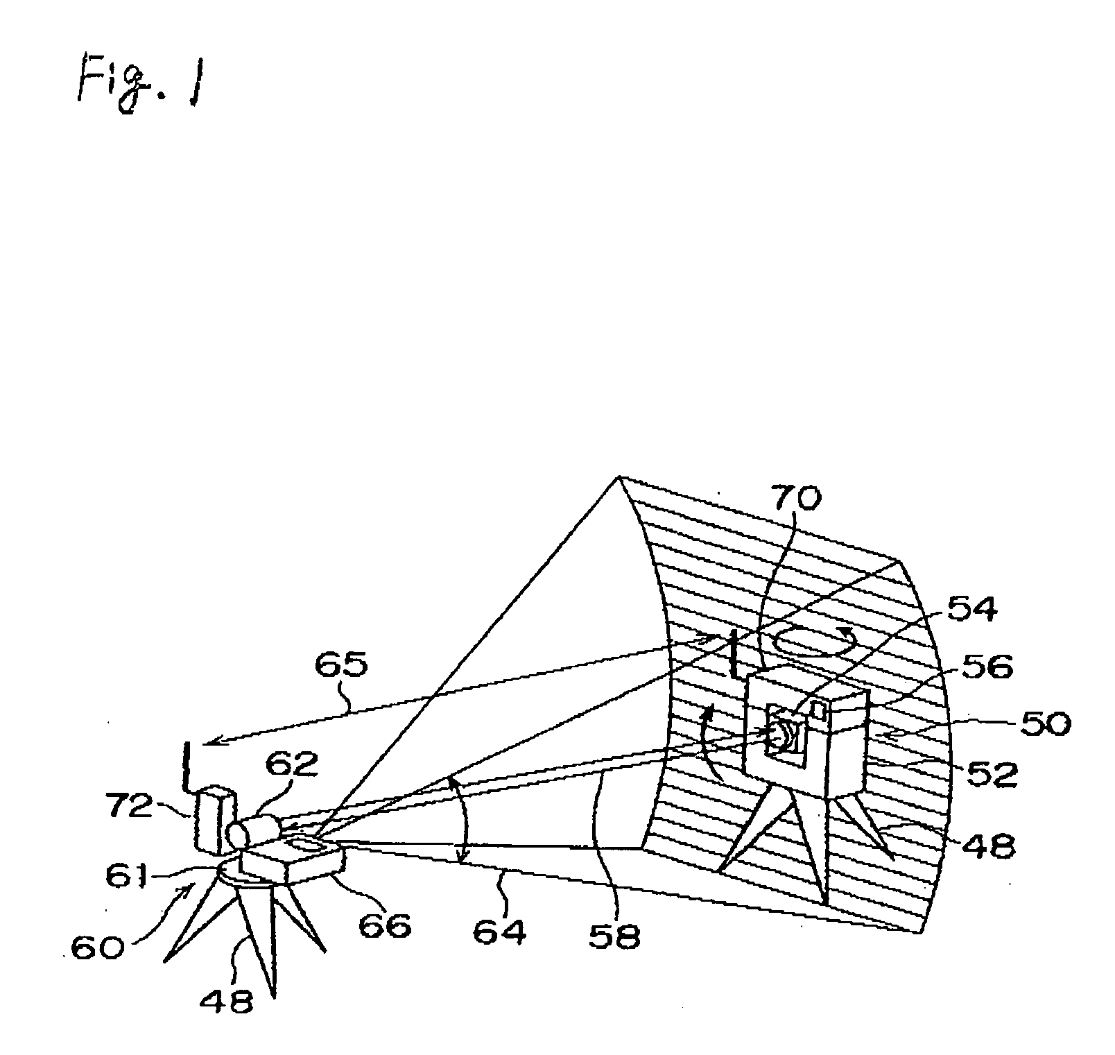
Figure 2 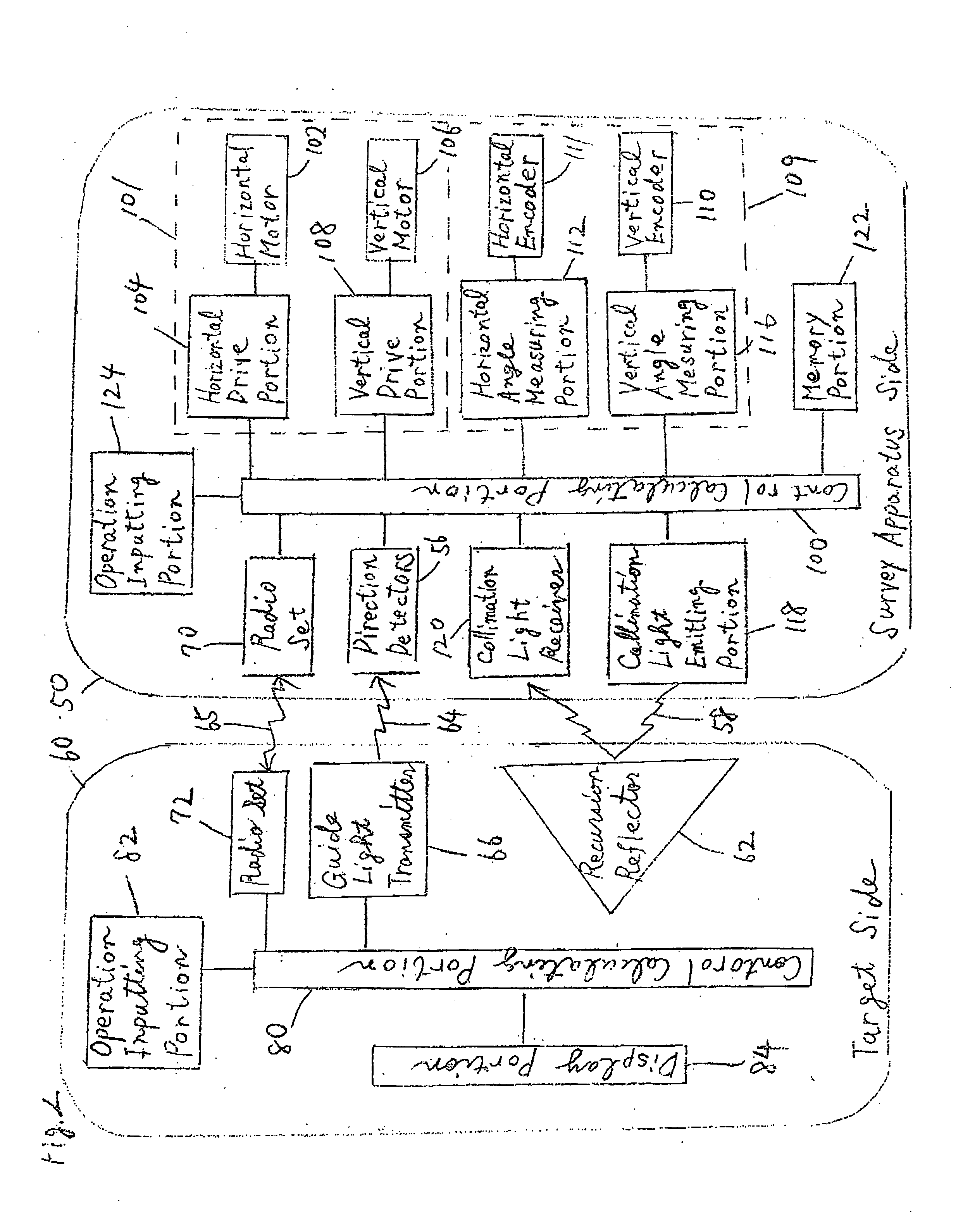
Figure 3
Abstract
Description
FIELD OF THE INVENTION
[0001] The present invention relates to a survey system capable of remotely controlling a surveying instrument from the side of a target by a single person. BACKGROUND OF THE INVENTION
[0002] Conventionally, an operator has been forced by necessity of collimating a target placed on a survey point through manual operations when the position of the survey point or the like is measured by a surveying instrument such as a total station (electronic distance / angle meter). In recent years, a surveying instrument capable of automatically collimating a target by means of an automatic collimator has been proposed in order to lessen the labor of the operator and reduce collimation errors committed by the operator. The surveying instrument provided with the automatic collimator can automatically direct a telescope toward a target by calculating the direction of the target in such a way as to emit collimation light along the optical axis of the telescope of the surveying i...
Examples
Embodiment Construction
[0019] As is apparent from the foregoing description, according to the survey system, it becomes possible to restart the process for searching proper guide light by, from the side of the target, commanding the surveying instrument to continuously perform the operation even when disturbing light or noise light is erroneously regarded as guide light during the search.
[0020] It becomes possible to more reliably search proper guide light by rotating the direction detector to a position deviating from a light receiving range within which the direction detector receives light other than guide light.
BEST MODE FOR CARRYING OUT THE INVENTION
[0021] An embodiment of the present invention will be hereinafter described in accordance with the attached drawings. FIG. 1 is a block diagram of a survey system showing one embodiment of the present invention, and FIG. 2 is a block diagram for explaining an internal structure of a surveying instrument and an internal structure of a target.
[0022] In ...