
Piezo inkjet printer
Patent Information
- Authority / Receiving Office
- US · United States
- Current Assignee / Owner
- Publication Date
- 2006-09-21
- Estimated Expiration
- Not applicable · inactive patent
Smart Images
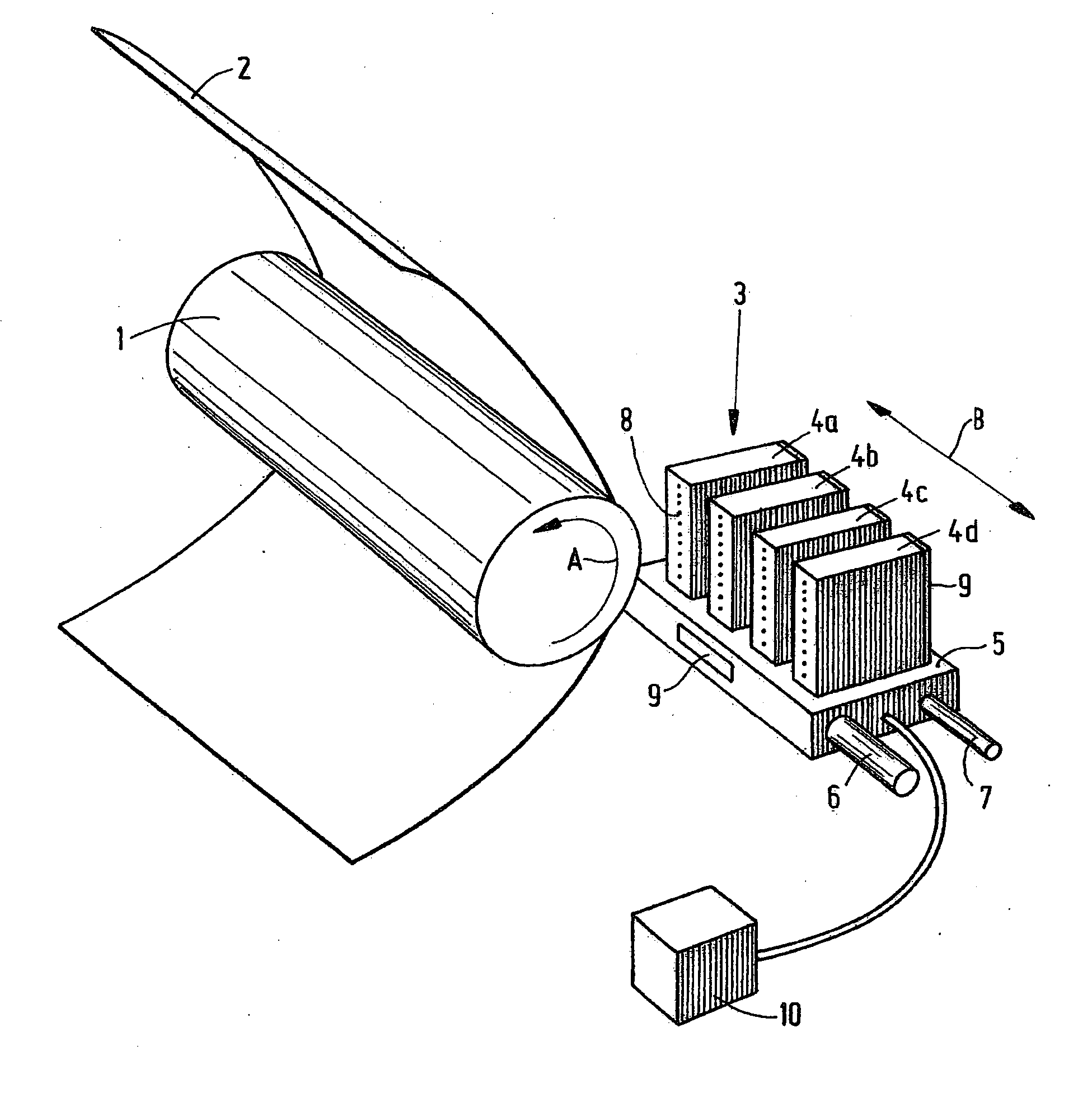
Figure 1 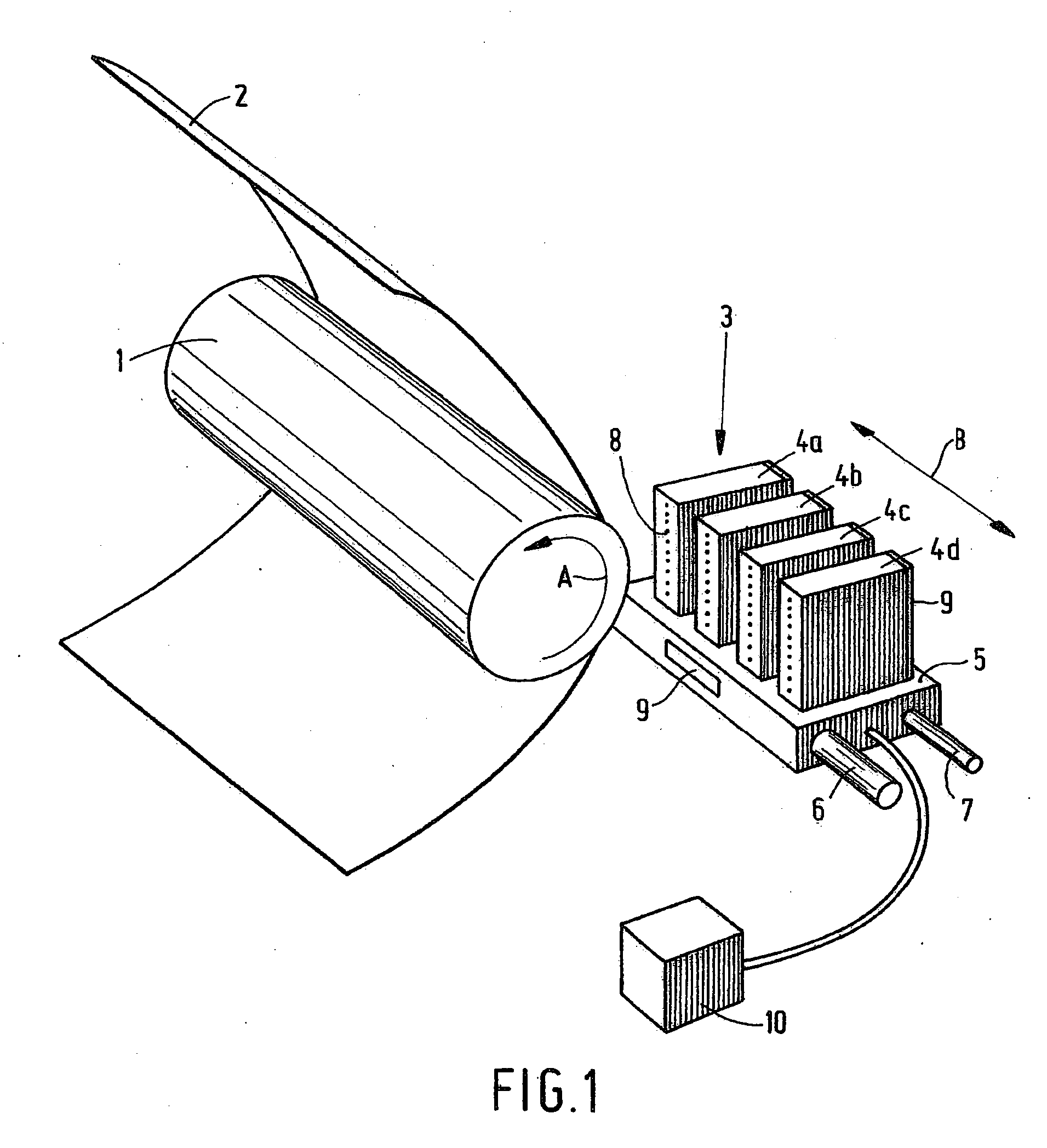
Figure 2 
Figure 3
Abstract
Description
[0001] This application claims priority to Dutch Patent Application No. 1028546 filed on Mar. 15, 2005 in The Netherlands, the entire contents of which is hereby incorporated by reference in its entirety. BACKGROUND OF THE INVENTION
[0002] The present invention relates to an inkjet printer containing a substantially closed ink duct and a transducer that is substantially parallel to the closed duct, this transducer deforming by actuation in order to generate a pressure wave in the duct.
[0003] An inkjet printer of this kind is known from U.S. Pat. No. 4,688,048. As is known from the prior art, actuation of a transducer of the above kind causes it to deform, so that a sudden volume change occurs in the duct (also referred to as “ink chamber”). This produces a pressure wave in the duct. If the pressure wave is strong enough, this leads to a drop of ink being ejected from the duct nozzle. In this manner, each individual actuation may lead to a drop of ink being ejected. By imposing such...
Examples
Embodiment Construction
[0016]FIG. 1 is a diagram showing an inkjet printer. According to this embodiment, the printer comprises a roller 1 used to support a receiving medium 2, such as a sheet of paper or a transparency, and move it across a carriage 3. The carriage comprises a carrier 5 to which four printheads 4a, 4b, 4c and 4d have been fitted. Each printhead contains its own color, in this case cyan (C), magenta (M), yellow (Y) and black (K), respectively. The printheads are heated using heating elements 9, which have been fitted to the rear of each printhead 4 and to the carrier 5. The temperature of the printheads is maintained at the correct level by the application of a central control unit 10 (controller).
[0017] The roller 1 rotates around its own axis as indicated by arrow A. In this manner, the receiving medium may be moved in the sub-scanning direction (often referred to as the X direction) relative to the carrier 5, and therefore also relative to the printheads 4. The carriage 3 may be moved...