
Testing plate and test method using the same
Patent Information
- Authority / Receiving Office
- US · United States
- Current Assignee / Owner
- Publication Date
- 2006-02-23
- Estimated Expiration
- Not applicable · inactive patent
Smart Images
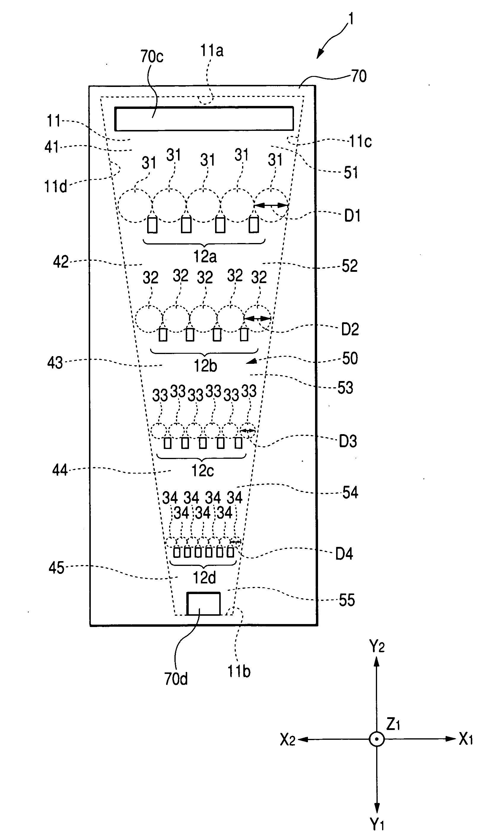
Figure 1 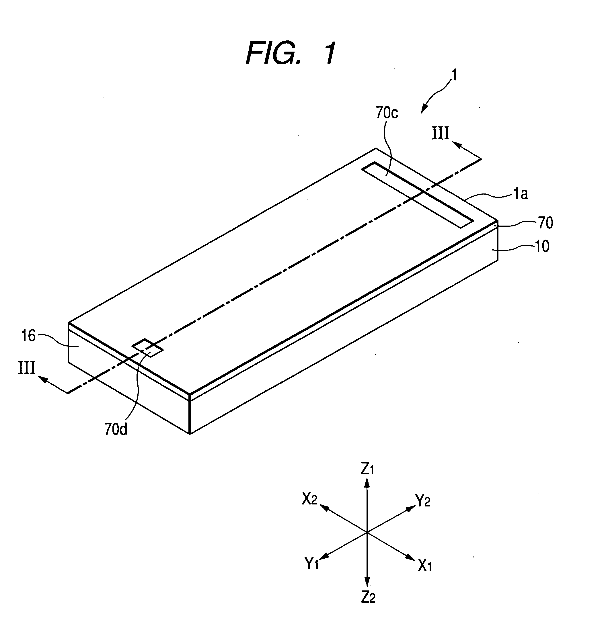
Figure 2 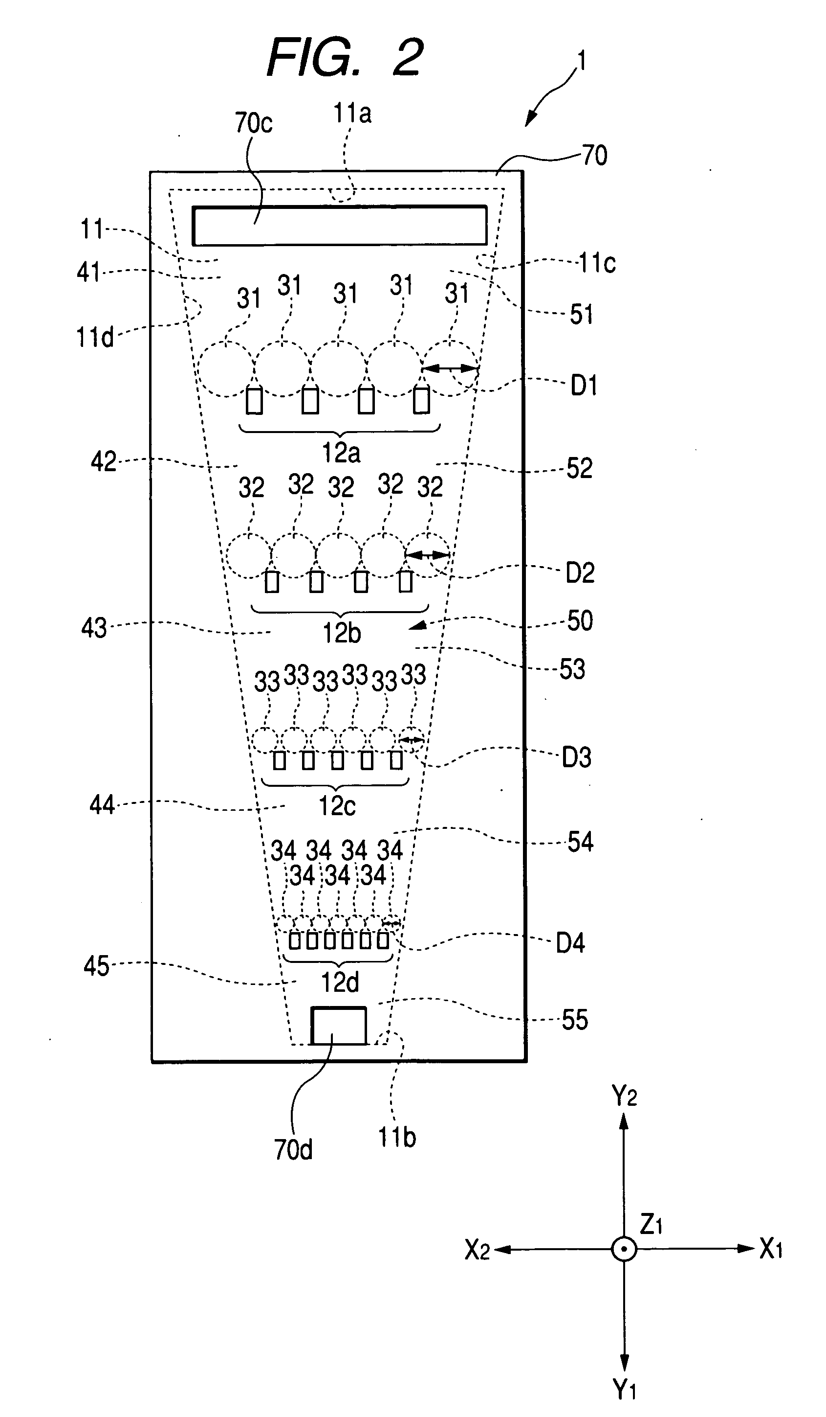
Figure 3
Abstract
Description
BACKGROUND OF THE INVENTION
[0001] 1. Field of the Invention
[0002] The present invention relates to a simple testing plate used for performing a blood test, a urine test, or a DNA test by a medical institution or an individual, and to a method of manufacturing the same, and more specifically, to a testing plate capable of easily arranging particles having probes fixed thereon according to the kind of the probe and to a method of manufacturing the testing plate in which the particles are arranged.
[0003] 2. Description of the Related Art
[0004] Recently, a testing chip for a collected material from the human body, such as blood or urine, has been developed. For example, a DNA chip where multiple kinds of DNA fragments (probes) are attached on a substrate, such as glass, can measure expression of gene (test sample or target) collected from the human body at one time.
[0005] When a biochemical reaction, which has been conventionally performed by a test tube, a dropper, an agitator or ...
Examples
first embodiment
[0029]FIG. 1 is a perspective view illustrating the appearance of a testing plate according to the invention. FIG. 2 is a plan view of the testing plate shown in FIG. 1, as viewed from an upper side (Z1 direction shown in FIG. 1), and FIG. 3 is a cross-sectional view illustrating a state where the testing plate shown in FIG. 1 is cut along the line III-III to be seen from an X1 direction of FIG. 1.
[0030] A testing plate 1 shown in FIG. 1 performs a predetermined test where a test sample, such as blood or urine, collected from the human body reacts to a predetermined reagent or the like. When the testing plate is used as, for example, a DNA chip, the collected test sample, such as blood, is subjected to a predetermined treatment, such as a fluorescent labeling treatment, to be used.
[0031] In the embodiment shown in FIG. 1, the testing plate 1 has a substantial-rectangular-parallelepiped shape which has a predetermined thickness to extend in the longitudinal direction (Y1-Y2 directio...
second embodiment
[0096]FIG. 11 is a plan view of a testing plate according to the present invention as viewed from an upper side (the Z1 direction shown in FIG. 11), and corresponds to FIG. 2. FIG. 12 is a cross-sectional view showing a state where the testing plate shown in FIG. 11 is cut along the line XII-XII to be seen from the X1 direction of FIG. 1. FIG. 13 is a plan view of a base body of a testing plate 100 shown in FIG. 11, as viewed from the upper side.
[0097] The testing plate 100 shown in FIGS. 11 and 12 has the same components as those of the testing plate 1 shown in FIGS. 1 to 3. Therefore, in the testing plate 100, the same numerals are attached to the same components as those of the testing plate 1 shown in FIGS. 1 to 3, and a description thereof will be omitted.
[0098] The difference between the testing plate 100 and the testing plate 1 shown in FIGS. 1 to 3 is a basic structure. As shown in FIG. 13, a concave portion 111 having a predetermined depth h2 is formed in a top surface 110...