
Radiation detector and x-ray CT apparatus provided therewith
Patent Information
- Authority / Receiving Office
- US · United States
- Current Assignee / Owner
- Publication Date
- 2016-01-21
Smart Images
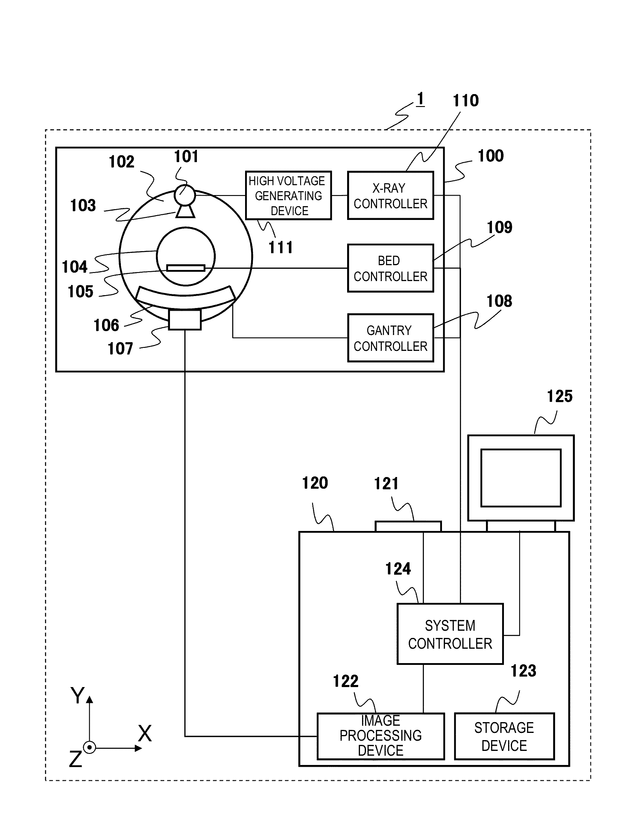
Figure 1 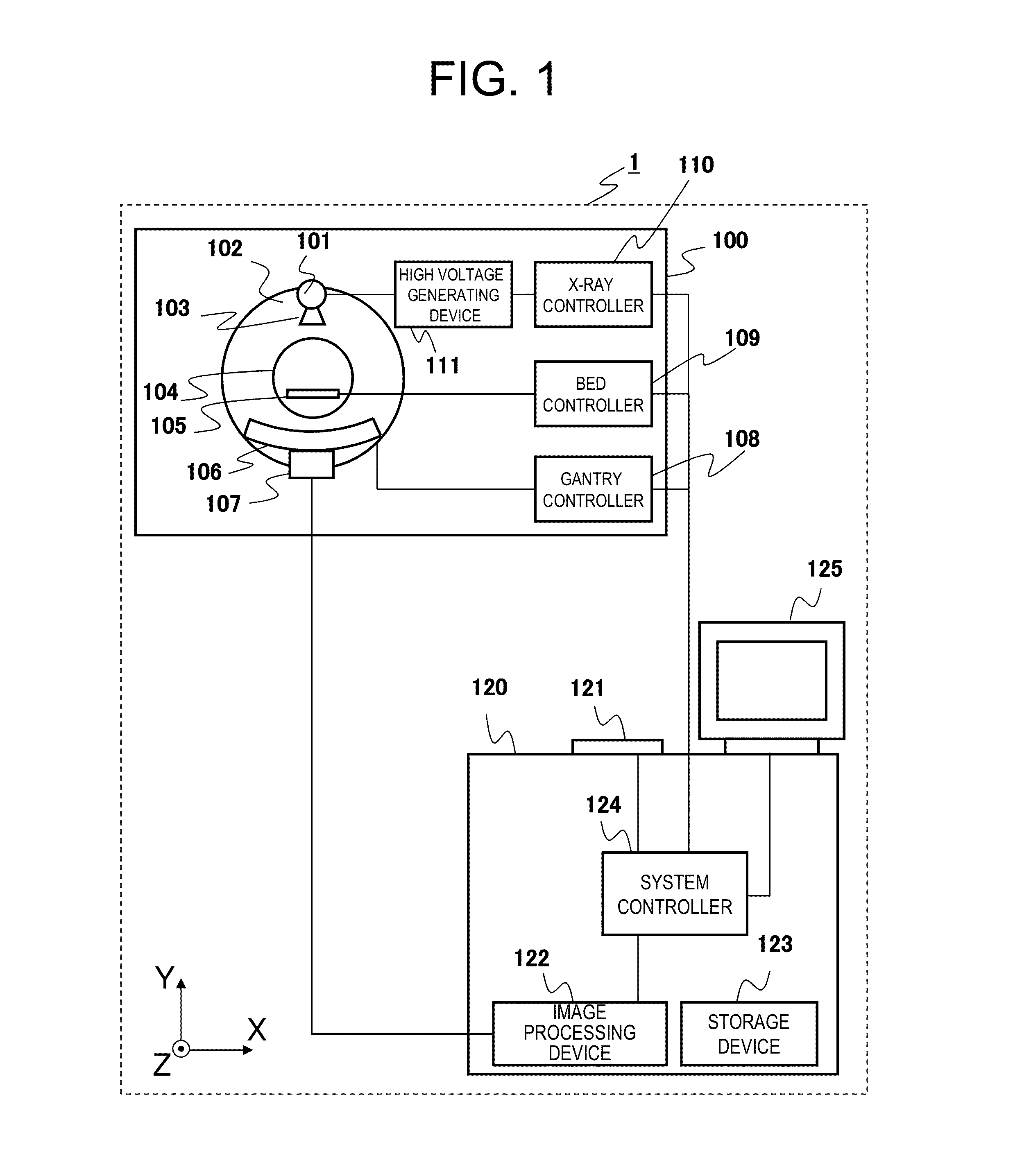
Figure 2 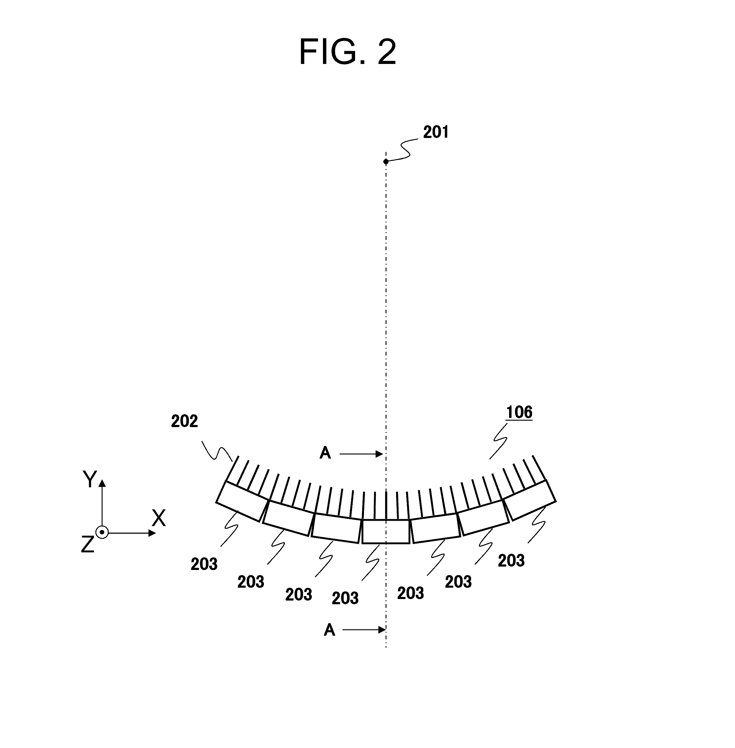
Figure 3
Abstract
Description
TECHNICAL FIELD
[0001] The present invention relates to a radiation detector detecting an X-ray, y-ray, etc., and particular to a support member supporting a collimator plate to be provided on the radiation source side of the radiation detector in order to remove scattered radiations. The present invention relates also to an X-ray Ct apparatus provided with such a radiation detector.BACKGROUND ART
[0002] An X-ray CT (Computed Tomography) apparatus that is one of medical image diagnostic apparatuses reconstructs a tomographic image of an object using projection data from multiple angles that can be obtained by rotating an X-ray tube device irradiating an X-ray to the object and an X-ray detector detecting distribution of the X-ray dose transmitted through the object as the projection data around the object to display the reconstructed tomographic image. The image to be displayed on the X-ray CT apparatus draws organ shapes inside the object and is used for image diagnosis.
[0003] As a radi...
Examples
first embodiment
[0026]First, the overall configuration of the X-ray CT apparatus of the present invention that is an example of medical image diagnostic apparatuses will be described using FIG. 1. FIG. 1 is a block diagram showing the overall configuration of the X-ray CT apparatus 1. As shown in FIG. 1, the X-ray CT apparatus 1 comprises the scan gantry unit 100 and the operation unit 120.
[0027]The scan gantry unit 100 comprises the X-ray tube device 101, the rotating disk 102, the collimator 103, the X-ray detector 106, the data collection device 107, the bed device 105, the gantry controller 108, the bed controller 109, the X-ray controller 110, and the high voltage generating device 111.
[0028]The X-ray tube device 101 is a device for irradiating an X-ray to an object placed on the bed device 105. The collimator 103 is a device for restricting a radiation range of an X-ray irradiated from the X-ray tube device 101. The rotating disk 102 is equipped with the X-ray tube device 101 and the X-ray de...
second embodiment
[0055]The second embodiment will be described using FIG. 7. The point different from the first embodiment is that X-ray detection elements have irregular gaps partly in the rotation axis direction (parallel to the Z axis), and the same descriptions will be omitted because the others are the same as the first embodiment. Additionally, FIG. 7 can be substituted for FIG. 4 of the first embodiment.
[0056]Depending on the material and the number of the collimator plate support members 323, there is a case of lacking the mechanical strength of the collimator plate support members 323 formed thinner than gaps between X-ray detection elements aligned along the rotation axis direction to support the collimator plates 321. In order to supplement the insufficient mechanical strength of the collimator plate support members 323, the thickness of the collimator plate support members 323 should be increased. However, if the collimator plate support members 323 are thicker than the gaps between the ...
third embodiment
[0059]The third embodiment will be described using FIGS. 8 and 9. The point different from the first embodiment is that the pillars 721 and the grooved flat plates 722 are used instead of the grooved pillars 322, and the same descriptions will be omitted because the others are the same as the first embodiment. Additionally, FIG. 8 can be substituted for FIG. 3 of the first embodiment. Also, FIG. 9 is the E-E cross-sectional diagram in FIG. 8 and can be substituted for FIG. 5 of the first embodiment.
[0060]The pillars 721 support the grooved flat plates 722 and are installed on the substrate 333. The height of the pillars 721 is lower than the height of which the light detection element array 332, the scintillator element array 331, the collimator plate support members 323, and the collimator plate 321 are assembled.
[0061]The grooved flat plates 722 support the collimator plate 321 from the rotation axis direction and are installed on the upper ends of the pillars 721. The grooved fla...