
Mounting structure for EA material
a technology of mounting structure and ea material, which is applied in the direction of roofs, doors, pedestrian/occupant safety arrangements, etc., can solve the problems of troublesome operation and abnormal noise, and achieve the effect of improving the workability of the mounting operation of ea material and good ea characteristi
Patent Information
- Authority / Receiving Office
- US · United States
- Patent Type
- Applications(United States)
- Current Assignee / Owner
- Publication Date
- 2007-04-26
- Estimated Expiration
- Not applicable · inactive patent
Smart Images
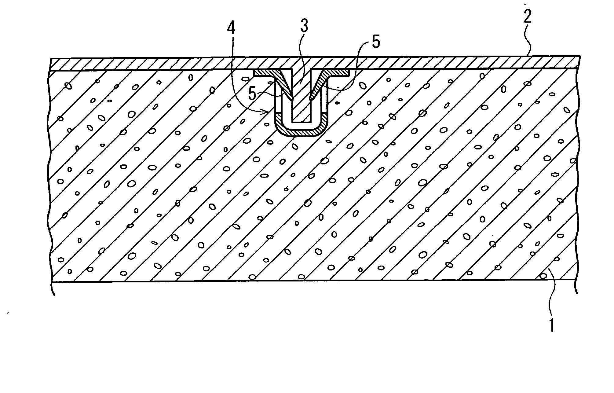
Figure 1 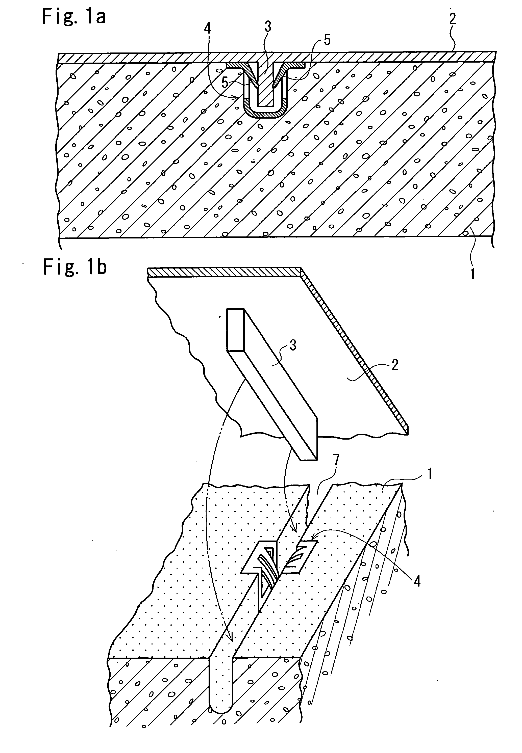
Figure 2 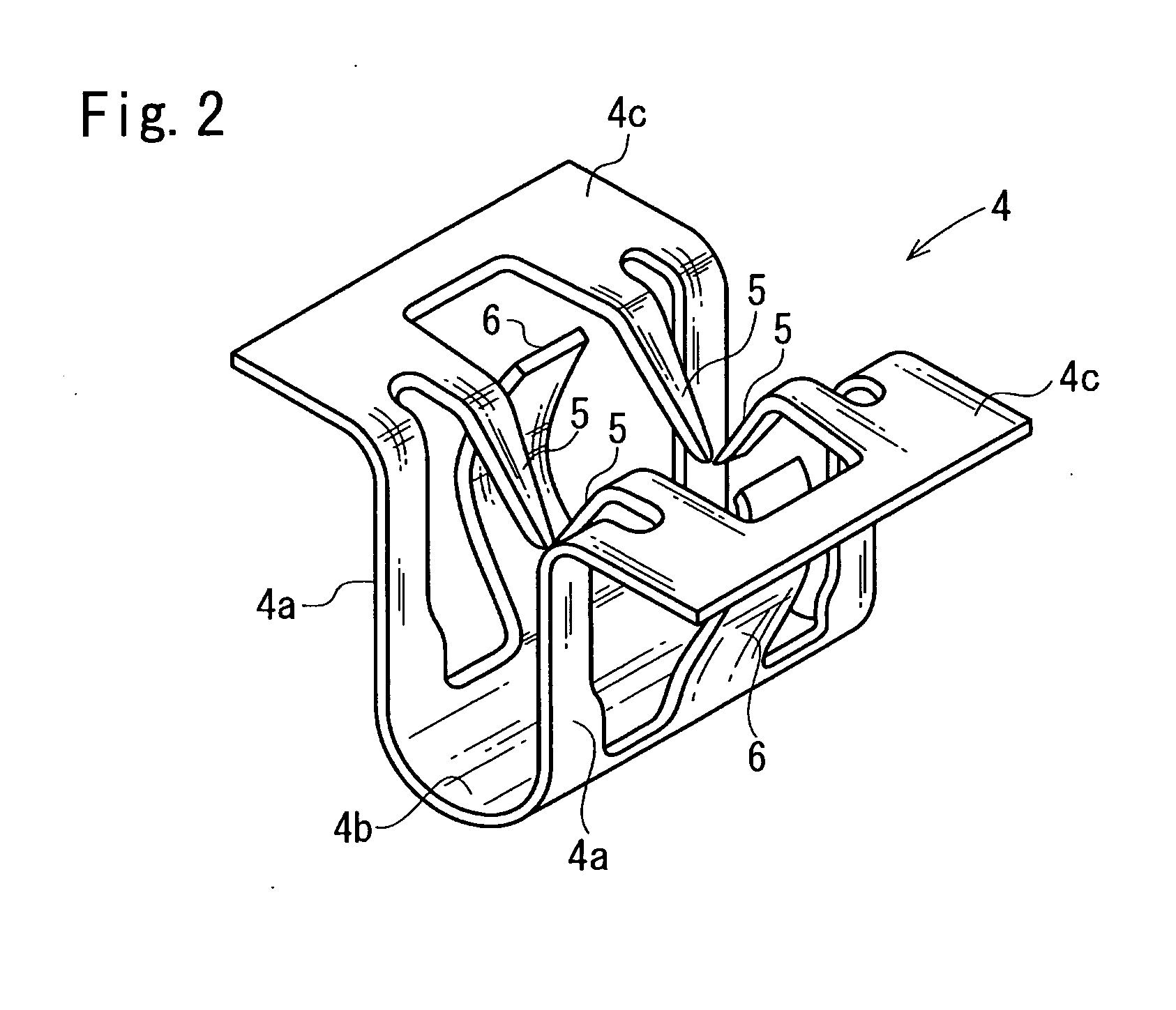
Figure 3
Abstract
Description
CROSS REFERENCE TO RELATED APPLICATION
[0001] This is a continuation application of PCT / JP2005 / 007430 filed on Apr. 19, 2005.TECHNICAL FIELD
[0002] The present invention relates to a mounting structure for an EA material (an impact energy absorbing material), and more particularly to a mounting structure for an EA material suitable for use in a trim of an automobile. BACKGROUND ART
[0003] For impact energy absorption (Energy Absorption: EA) in the event of a collision on a side (a lateral collision), an EA material made of rigid urethane is mounted to a door trim of an automobile. As a method for mounting the EA material made of rigid urethane to the door trim, Japanese Unexamined Patent Application Publication No. 2001-322507 describes the structure illustrated in FIGS. 7, 8a, and 8b. FIG. 7 is a cross-sectional view illustrating a mounting structure for an EA material described in FIG. 7 of the above publication. FIG. 8a is a perspective view of a cap (a cylindrical member) 20 use...
Examples
Embodiment Construction
[0050] With reference to the drawings, embodiments will be described. FIG. 1a is a cross-sectional view in an approximately horizontal direction illustrating a mounting structure for an EA material according to an embodiment. FIG. 1b is a perspective view illustrating the engaging relationship between a rib and a clip in the mounting structure for an EA material. FIG. 2 is a perspective view of the clip, and FIG. 3 is a perspective view illustrating a state in which the EA material is being mounted. FIGS. 4 and 5 are cross-sectional views and a perspective view for explaining a method of manufacturing the EA material having the rib, respectively.
[0051] As illustrated in FIG. 1, an EA material 1 made of synthetic resin foam such as rigid urethane foam is mounted to a trim (a door trim in the present embodiment) 2 made of a synthetic resin, which serves as a member, via a rib 3 and a clip 4. In the present embodiment, the clip 4 made of a ferromagnetic metal (e.g., iron) is integrall...