
Fixture, fixing assembly, and fixation method for fixing power line to base member
Patent Information
- Authority / Receiving Office
- US · United States
- Current Assignee / Owner
- Publication Date
- 2017-04-13
Smart Images
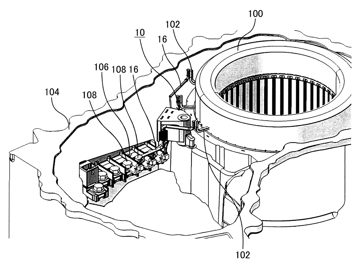
Figure 1 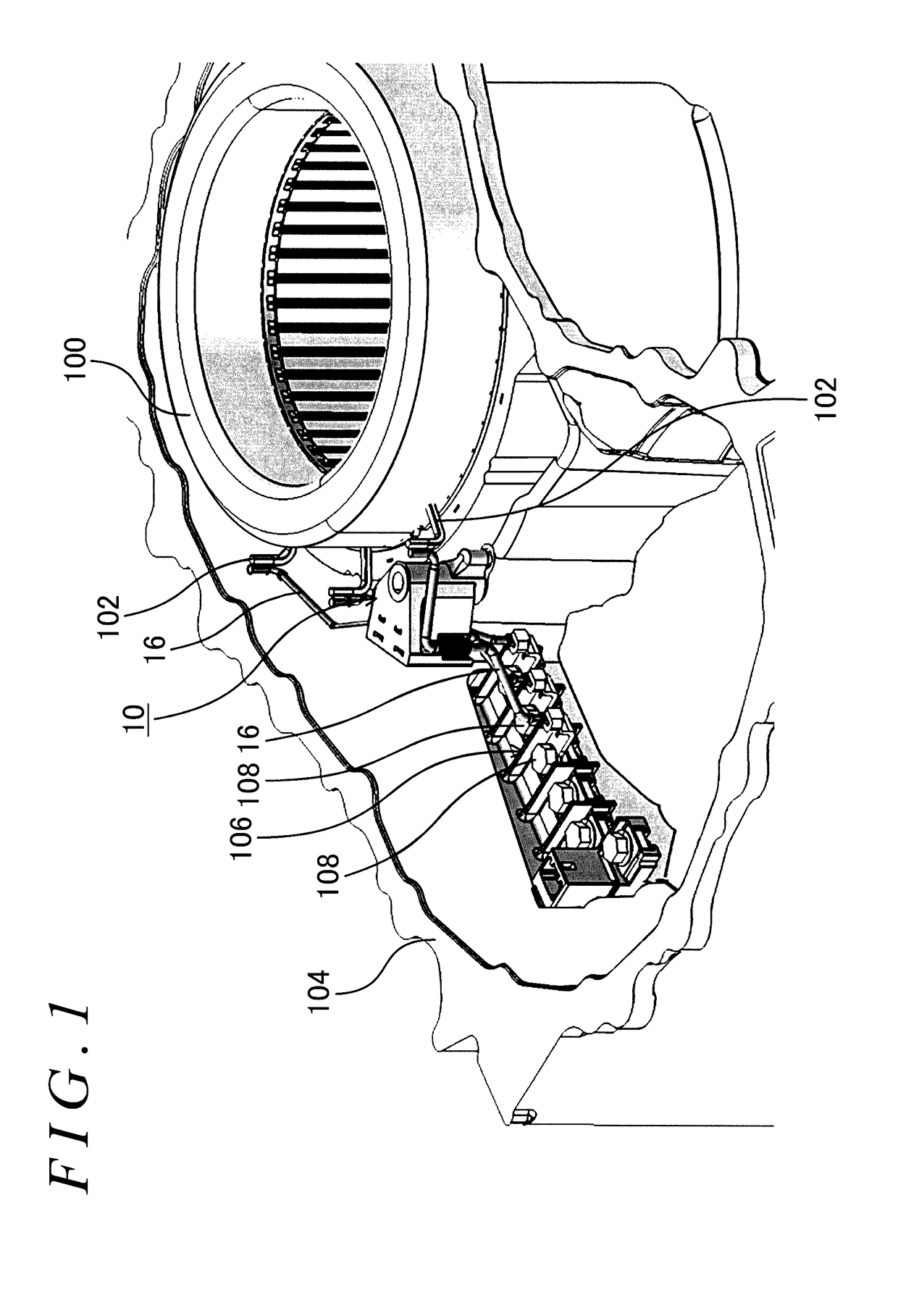
Figure 2 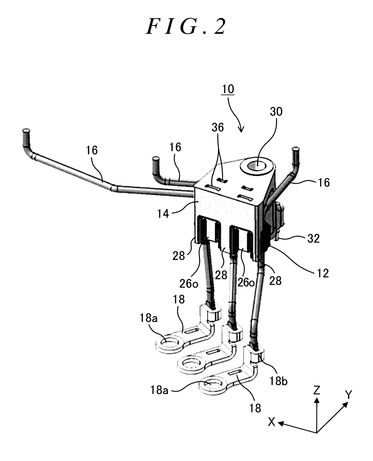
Figure 3
Abstract
Description
CROSS-REFERENCE TO RELATED APPLICATIONS
[0001] This application claims priority from Japanese Patent Application No. 2015-199270 filed on Oct. 7, 2015, the disclosure of which, including the specification, drawings and abstract, is incorporated herein by reference in its entirety.BACKGROUND
[0002] 1. Technical Field
[0003] The present disclosure relates to a fixture, a fixing assembly, and a fixation method each for fixing, to a base member, a power line connected to a rotary electric machine.
[0004] 2. Description of Related Art
[0005] Conventionally, there has been known an in-vehicle rotary electric machine provided in an electrically driven vehicle such as a hybrid vehicle or an electric vehicle. A power line for supplying an electric power from a power source is connected to such a rotary electric machine. Generally, one end of the power line is connected to a stator coil, and the other end of the power line is connected to a terminal block attached to a motor case. Further, in most case...
Examples
Embodiment Construction
[0033]Exemplary embodiments will be described below with reference to drawings. FIG. 1 is a view illustrating a state where power lines 16 are fixed by use of a fixing assembly 10 according to an exemplary embodiment. Further, FIG. 2 is a perspective view of the fixing assembly 10, and FIG. 3 is a perspective view of a holding jig 12. Further, FIG. 4 is a side view of a fixture 14, FIG. 5 is a front view of the fixture 14, FIG. 6 is a sectional view of the fixing assembly 10 taken along a line A-A in FIG. 5, and FIG. 7 is a sectional view taken along a line B-B in FIG. 6. Further, in the following description, in order to facilitate the description, a longitudinal direction of the holding jig 12 is referred to as an “X-direction,” a short direction thereof is referred to as a “Y-direction,” and a direction perpendicular to the X-direction and the Y-direction is referred to as a “Z-direction.”
[0034]The fixing assembly 10 of the present embodiment fixes, to a motor case 104 as a base ...