
Rivet tool for steel studs
Patent Information
- Authority / Receiving Office
- US · United States
- Current Assignee / Owner
- Publication Date
- 2009-02-12
- Estimated Expiration
- Not applicable · inactive patent
Smart Images
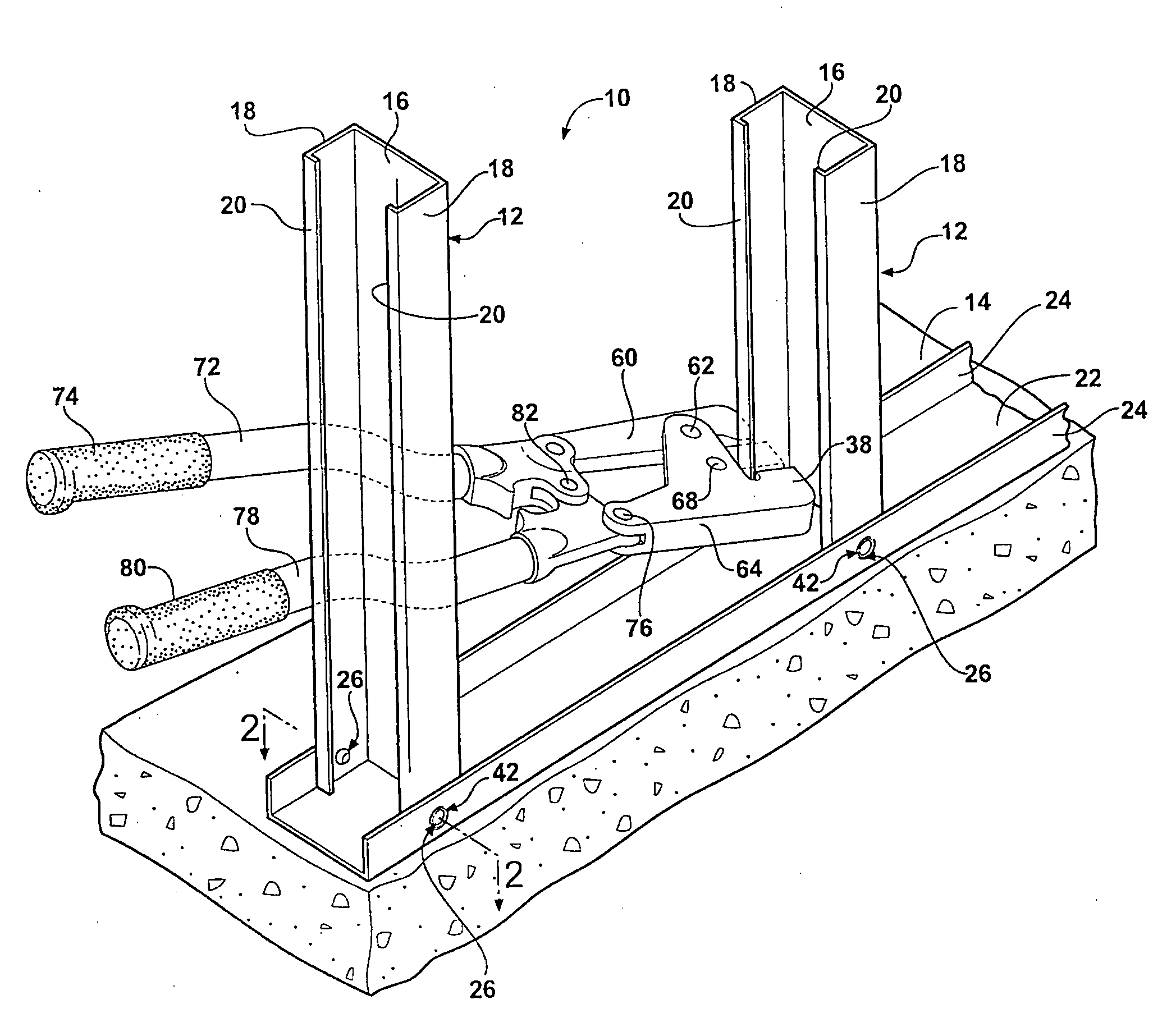
Figure 1 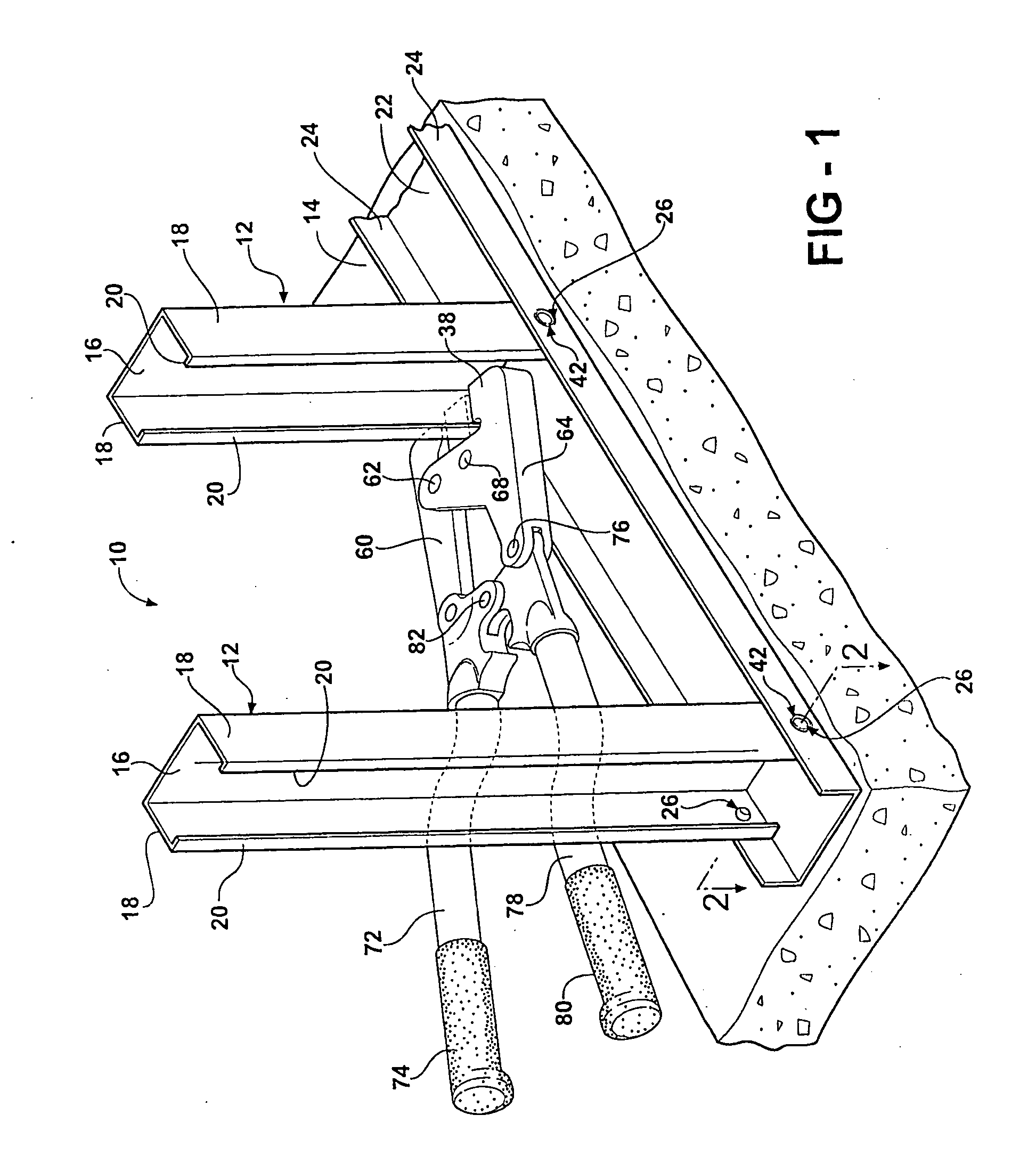
Figure 2 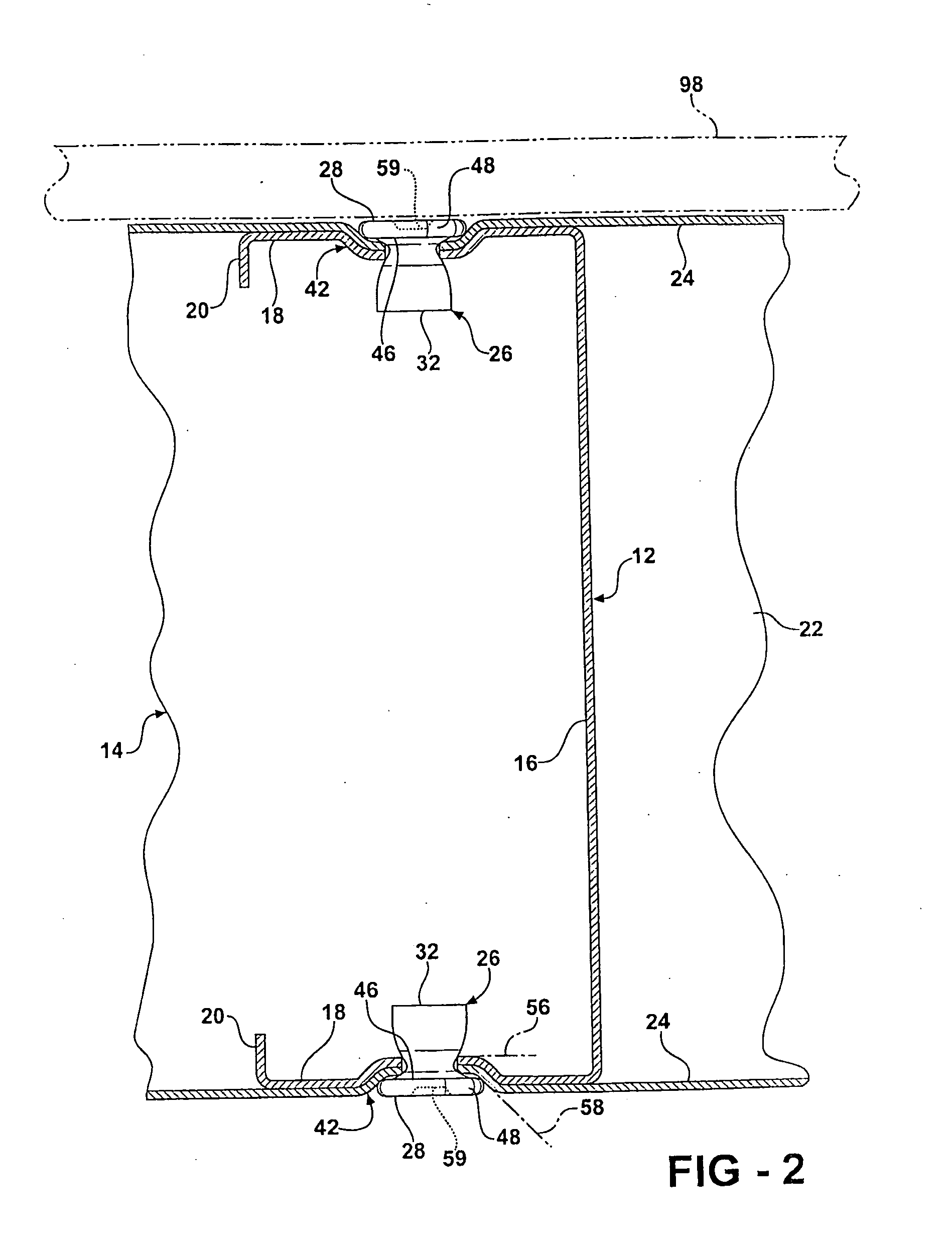
Figure 3
Abstract
Description
RELATED APPLICATIONS
[0001] This invention relates to, and claims the benefit of priority from U.S. Provisional Application No. 60 / 619,187 filed Oct. 15, 2004.BACKGROUND OF THE INVENTION
[0002] 1. Field of the Invention
[0003] The invention relates generally to a method and apparatus for fastening two overlapping sheets of metal with a deformable rivet, and more specifically toward an apparatus and method for fastening steel framing members with a rivet whose head is used to form a multi-contoured pocket in the sheet metal members.
[0004] 2. Related Art
[0005] Steel framing members are used in the construction industry to fabricate walls and other structural elements. Unlike wood, steel framing does not warp, shrink or split. It is not vulnerable to termites or carpenter ants. It will not rot, crumble, or add fuel to a fire. Because of this, and its strength and durability, steel framing has become a standard for commercial construction. Nevertheless, steel framing is used only in an estimate...
Examples
Embodiment Construction
[0021]Referring to the Figures, wherein like numerals indicate like or corresponding parts throughout several views, a typical steel frame wall 10 under construction is generally shown in FIG. 1 including vertical studs 12 fastened to a bottom track 14. The studs 12 and bottom track 14 are here used only for illustrative purposes as those skilled in the art will understand that other structural components, such as a top track, cross members, trusses, beams, brackets and the like also made from formed sheet metal can be joined in the same fashion as those components illustrated in FIG. 1. Therefore, while the following description will reference the joining of a stud 12 to a bottom track 14, it must be understood that any other sheet metal joining requirements can be addressed using the method and apparatus of the subject invention.
[0022]As is well-known in the art, the studs 12 of a steel frame wall 10 extend between opposite ends thereof and have a generally C-shaped cross-section....