
Card type wireless communication module
Patent Information
- Authority / Receiving Office
- US · United States
- Current Assignee / Owner
- Publication Date
- 2011-06-02
- Estimated Expiration
- Not applicable · inactive patent
Smart Images
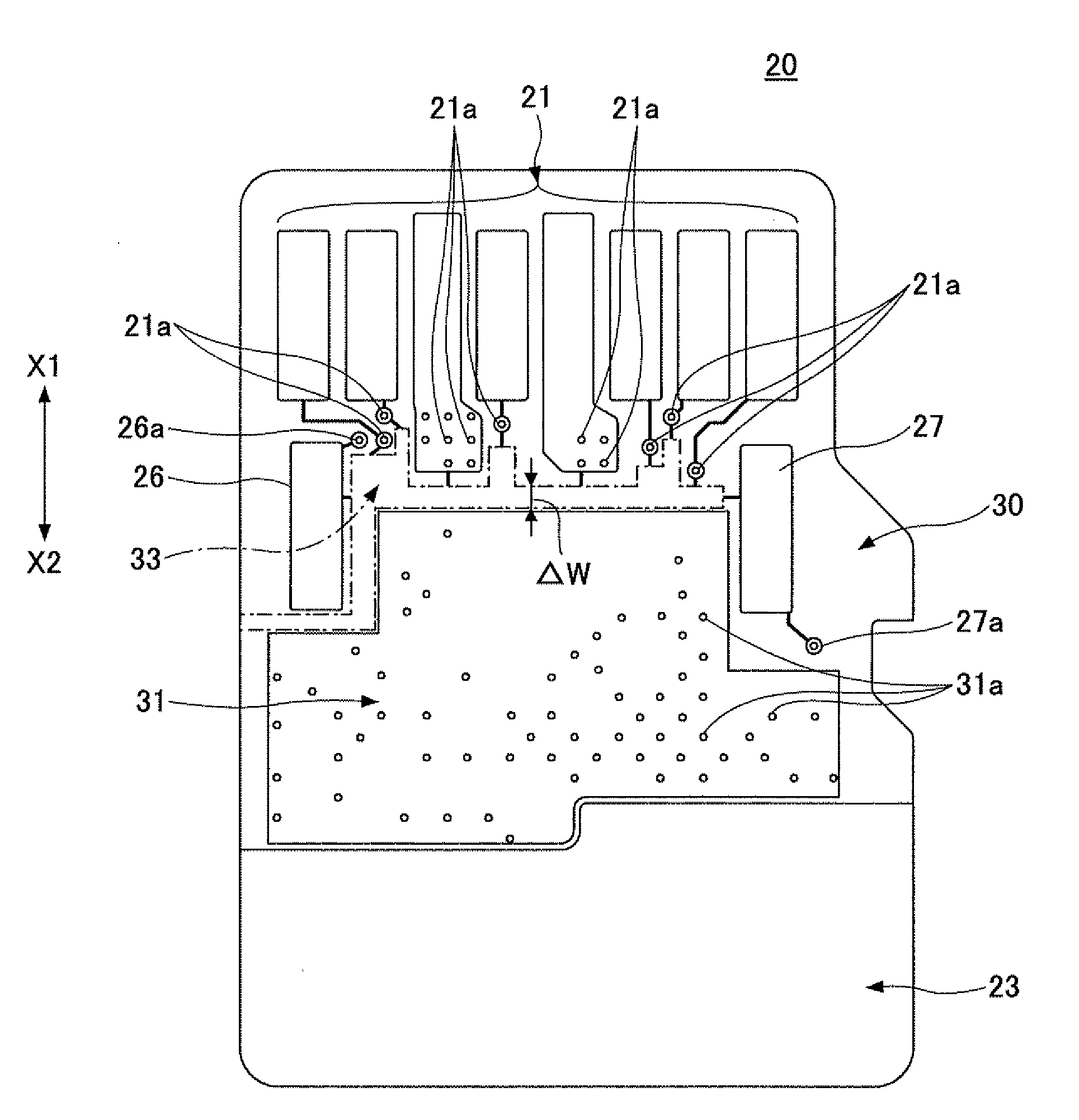
Figure 1 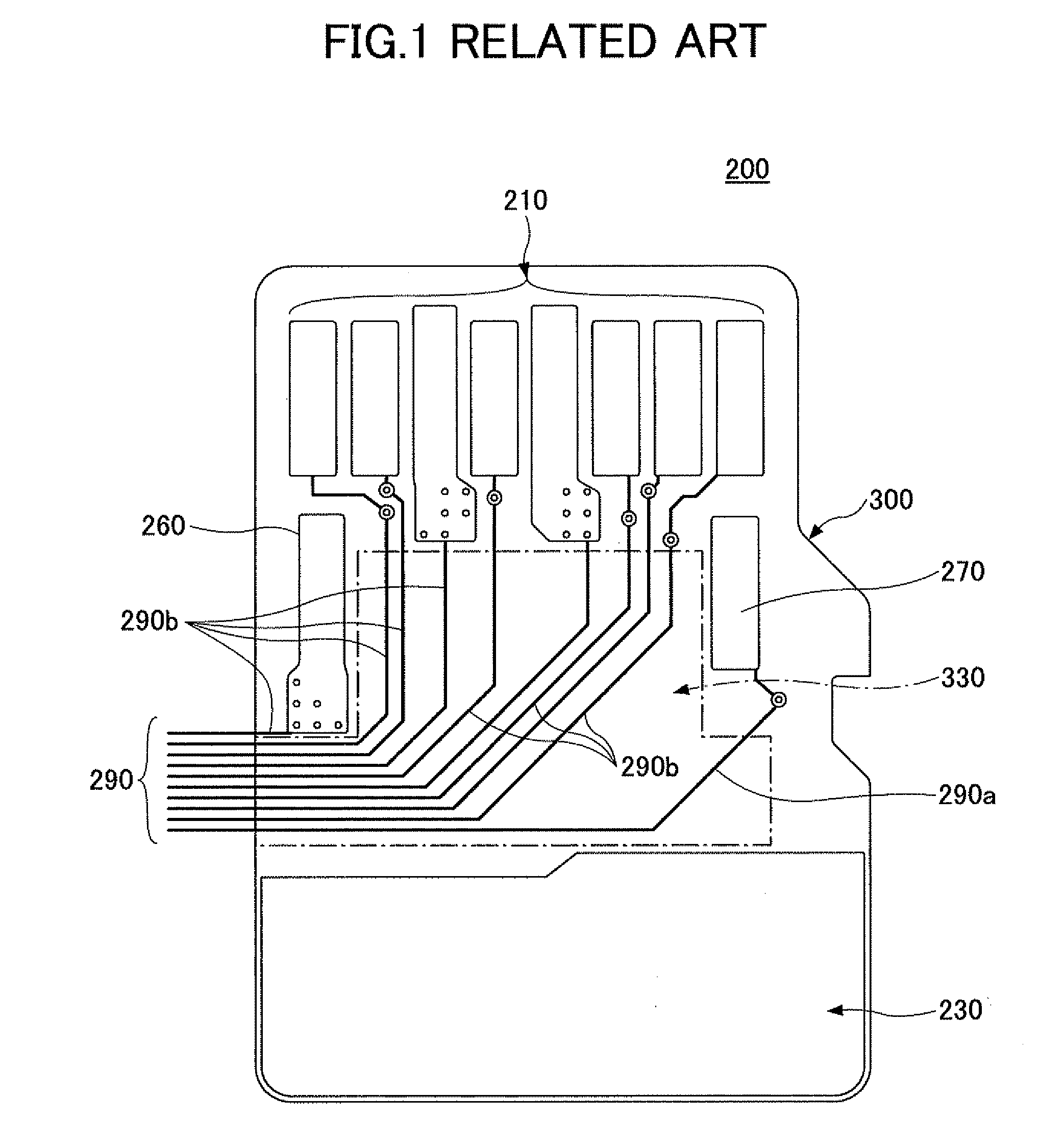
Figure 2 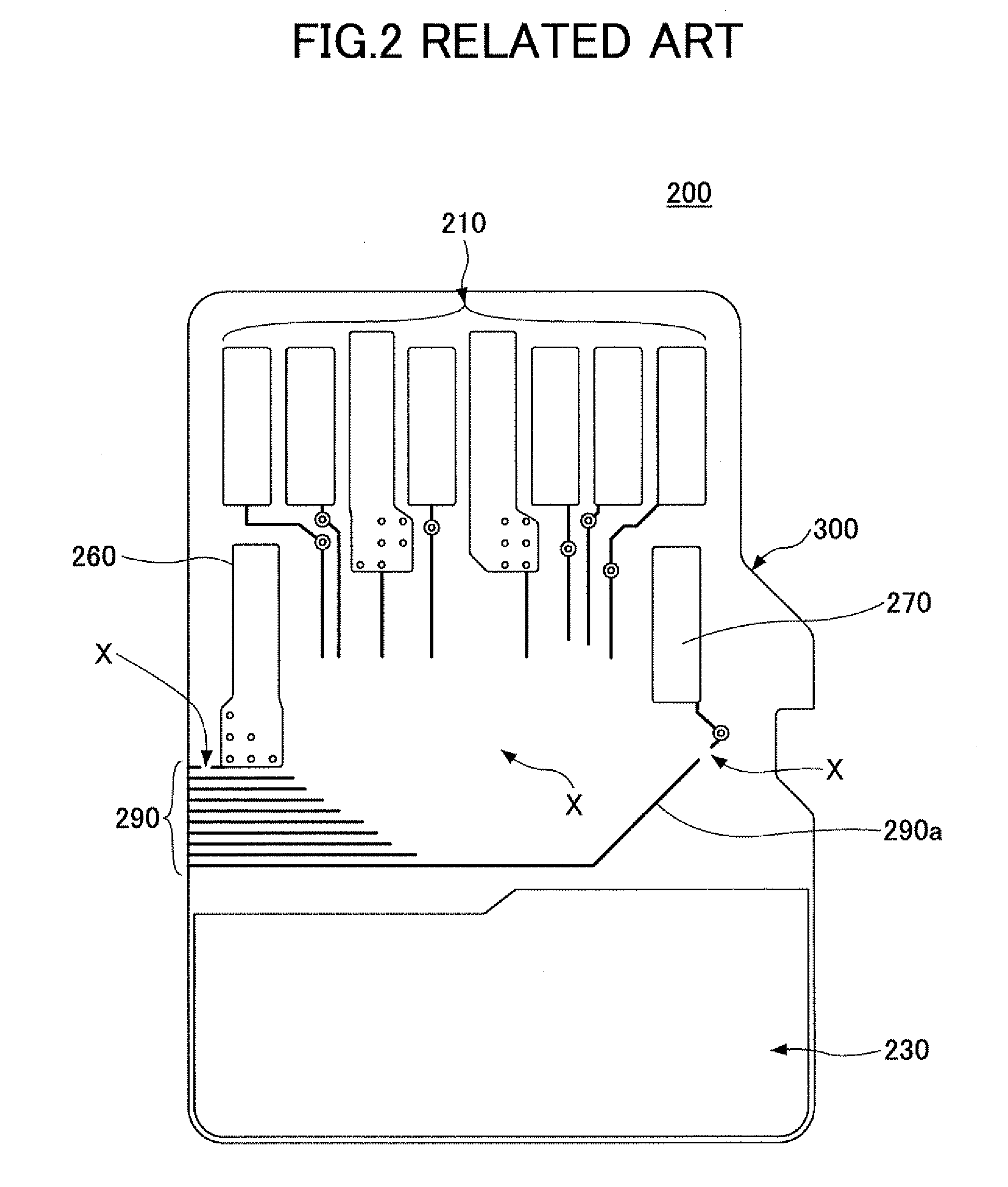
Figure 3
Abstract
Description
CROSS-REFERENCE TO RELATED APPLICATIONS
[0001] This patent application is based upon and claims the benefit of priority of Japanese Patent Application No. 2009-274982 filed on Dec. 2, 2009, the entire contents of which are incorporated herein by reference.BACKGROUND OF THE INVENTION
[0002] 1. Field of the Invention
[0003] The present invention generally relates to card type wireless communication modules. More specifically, the present invention relates to a card type wireless communication module including a high frequency terminal where a plating process is applied.
[0004] 2. Description of the Related Art
[0005] In a mobile communication terminal such as a portable phone, it is generalized that the terminal has a wireless function such as infrared or Bluetooth (registered trademark) transmitting and receiving for transferring data a short distance. In addition, it has been demanded that a function of a wireless LAN for transferring data an intermediate distance be additionally provided in ...
Examples
Embodiment Construction
[0033]A description is given below, with reference to the FIG. 3A through FIG. 11 of embodiments of the present invention.
[0034]FIG. 3A is a plan view showing a mobile communication terminal 10 where a card type wireless communication module 20 of an embodiment of the present invention is provided. FIG. 3B is a plan view of the card type wireless communication module 20 of the embodiment of the present invention. A state where a rear surface cover of the mobile communication terminal 10 is taken off is illustrated in FIG. 3A.
[0035]In the mobile communication terminal 10, a card device connector 12 is provided in the vicinity of a battery receiving position where a battery pack 11 is received. The card type wireless communication module 20 is inserted in a direction indicated by an arrow in the card device connector 12. The card type wireless communication module 20 has a structure whereby the card type wireless communication module 20 can be attached to or detached from the mobile c...