
Heatsink apparatus and electronic device having the same
a heatsink and electronic device technology, applied in the field of heatsink apparatuses, can solve the problems of increasing insufficient capacity of cooling electronic components generating a large amount of heat, enhancing the performance of the heat receiver, and reducing the efficiency of the heatsink, so as to achieve excellent cooling performance, high heat-receiving performance, and high operation stability
Patent Information
- Authority / Receiving Office
- US · United States
- Patent Type
- Applications(United States)
- Current Assignee / Owner
- Publication Date
- 2009-04-02
Smart Images
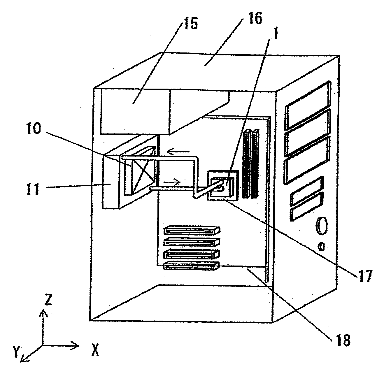
Figure 1 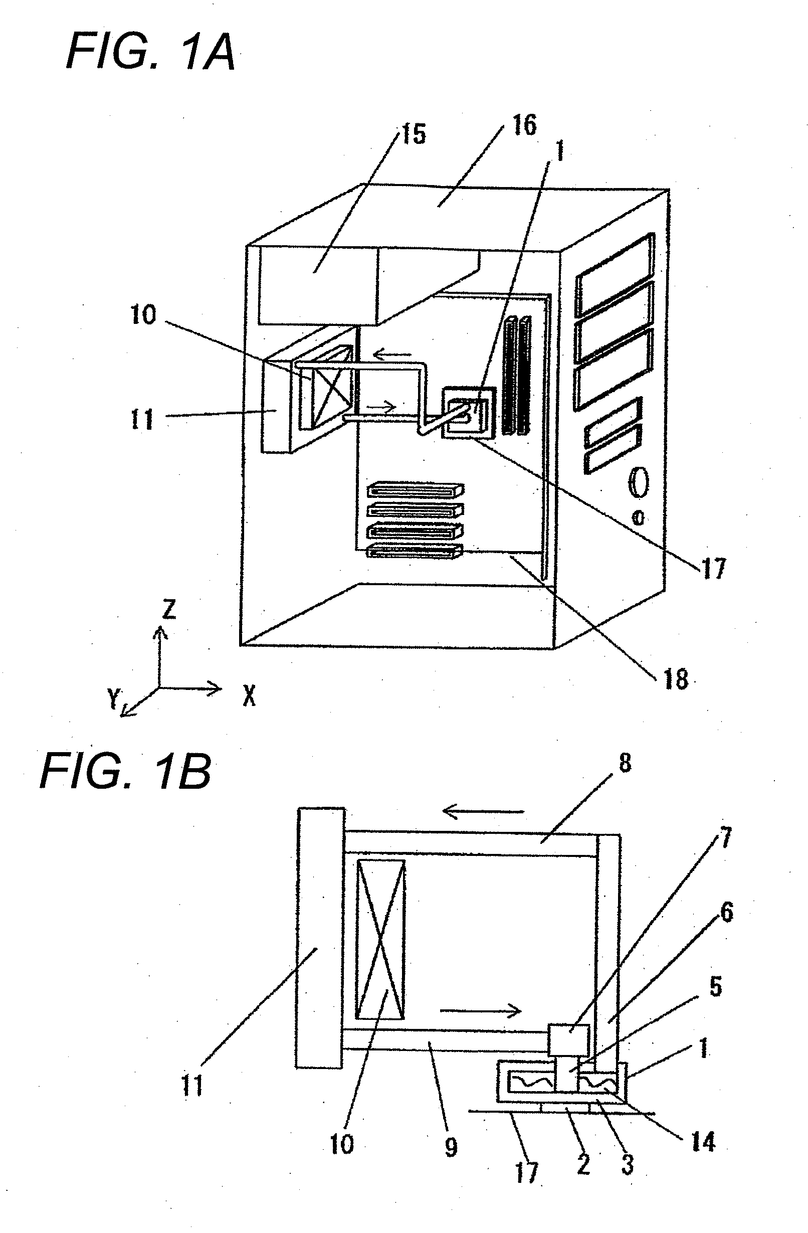
Figure 2 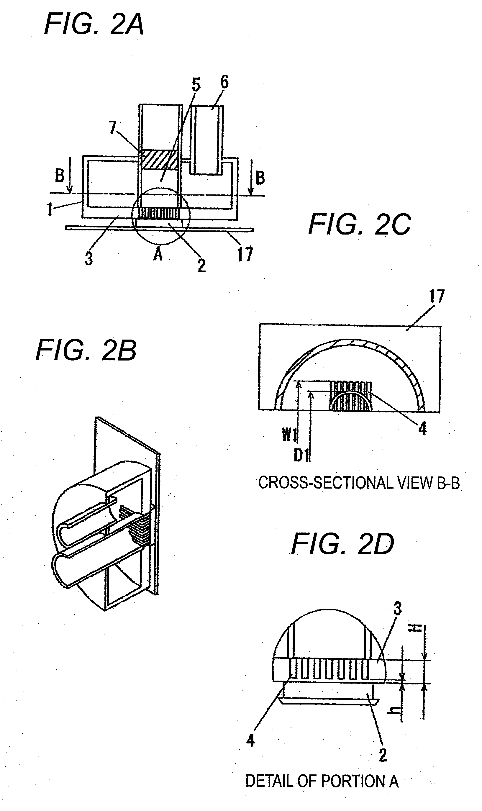
Figure 3
Abstract
Description
CROSS-REFERENCE TO RELATED APPLICATIONS
[0001] The present application claims priority under 35 U.S.C. §119 of Japanese Application Nos. 2007-254040 and 2007-254044 filed on Sep. 28, 2007, the disclosure of which is expressly incorporated by reference herein in its entirety.BACKGROUND OF THE INVENTION
[0002] 1. Field of the Invention
[0003] The present invention relates to heatsink apparatuses that cool semiconductors that produce heat, such as microprocessing units (hereinafter referred to as MPUs) used in personal computers and the like, and electronic components having heat-generating portions.
[0004] 2. Description of Related Art
[0005] With higher integration of electronic components, such as semiconductors, and higher frequency of operation clocks, electronic devices have recently been generating an increasing amount of heat. An increasingly important issue in view of normal operation of the electric components is how to maintain contact temperatures of the respective electronic compone...
Examples
first embodiment
[0080]FIG. 1A is a perspective view when a heatsink apparatus according to a first embodiment of the present invention is provided in a personal computer (hereinafter referred to as a PC) unit; and FIG. 1B illustrates a structure of the heatsink apparatus of the present invention. As shown in FIG. 1A, PC unit 16 includes the heatsink apparatus according to the present invention, along with PC components, such as power source unit 15, motherboard 18, and the like. The heatsink apparatus includes box-shaped heat-receiving unit 1, which is connected to socket 17 of a heat-generating body, heat dissipater 11; and fan 10, which cools heat dissipater 11.
[0081]More specifically, the heatsink apparatus according to the present invention includes three main components and circulation components, as shown in FIG. 1B. The three main components are box-shaped heat-receiving unit 1, which includes heat-receiving plate 3; heat dissipater 11; and check valve 7, which determines a circulation direc...
second embodiment
[0103]In a second embodiment, the slits of the first embodiment are provided radially. For explanation purposes, identical reference numerals are provided to components identical to those in the first embodiment, and specific explanations thereof in the first embodiment are referred to.
[0104]A heatsink apparatus according to the second embodiment of the present invention is explained with reference to FIGS. 5A to 8D. FIG. 8A is a central vertical cross-sectional view of an alternative heat-receiving unit according to the second embodiment of the present invention; FIG. 8B is a cross-sectional perspective view of the heat-receiving unit of FIG. 8A; FIG. 8C is a horizontal cross-sectional view of the heat-receiving unit of FIG. 8A; and FIG. 8D is a cross-sectional detail view of portion A shown in FIG. 8A. As shown in FIG. 8A, slits 4, which are provided in heat-receiving plate 3 of heat-receiving unit 1 immediately above a heat-generating body, have a radial shape extending from a ce...
third embodiment
[0105]In a third embodiment, slits are not provided at a central portion of heat-receiving plate 3 contacting with heat-generating body 2. For explanation purposes, identical reference numerals are provided to components identical to those in the first and second embodiments, and specific explanations thereof in the first and second embodiments are referred to.
[0106]A case where slits 4 are provided in parallel is first explained with reference to FIGS. 9A to 9D. FIG. 9A is a central vertical cross-sectional view of heat-receiving unit 1 according to the third embodiment of the present invention; FIG. 9B is a cross-sectional perspective view of the heat-receiving unit of FIG. 9A; FIG. 9C is a horizontal cross-sectional view of the heat-receiving unit of FIG. 9A; and FIG. 9D is a cross-sectional detail view of portion A shown in FIG. 9A. As shown in FIG. 9A, slits 4, which are provided substantially in parallel in heat-receiving plate 3 of heat-receiving unit 1 immediately above a he...