
Non-aqueous electrolyte and non-aqueous electrolyte secondary battery using the same
Patent Information
- Authority / Receiving Office
- US · United States
- Current Assignee / Owner
- Publication Date
- 2009-10-08
Smart Images
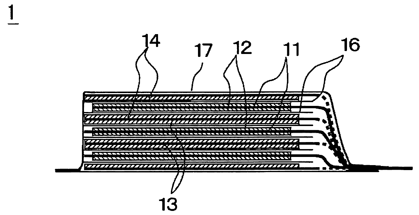
Figure 1 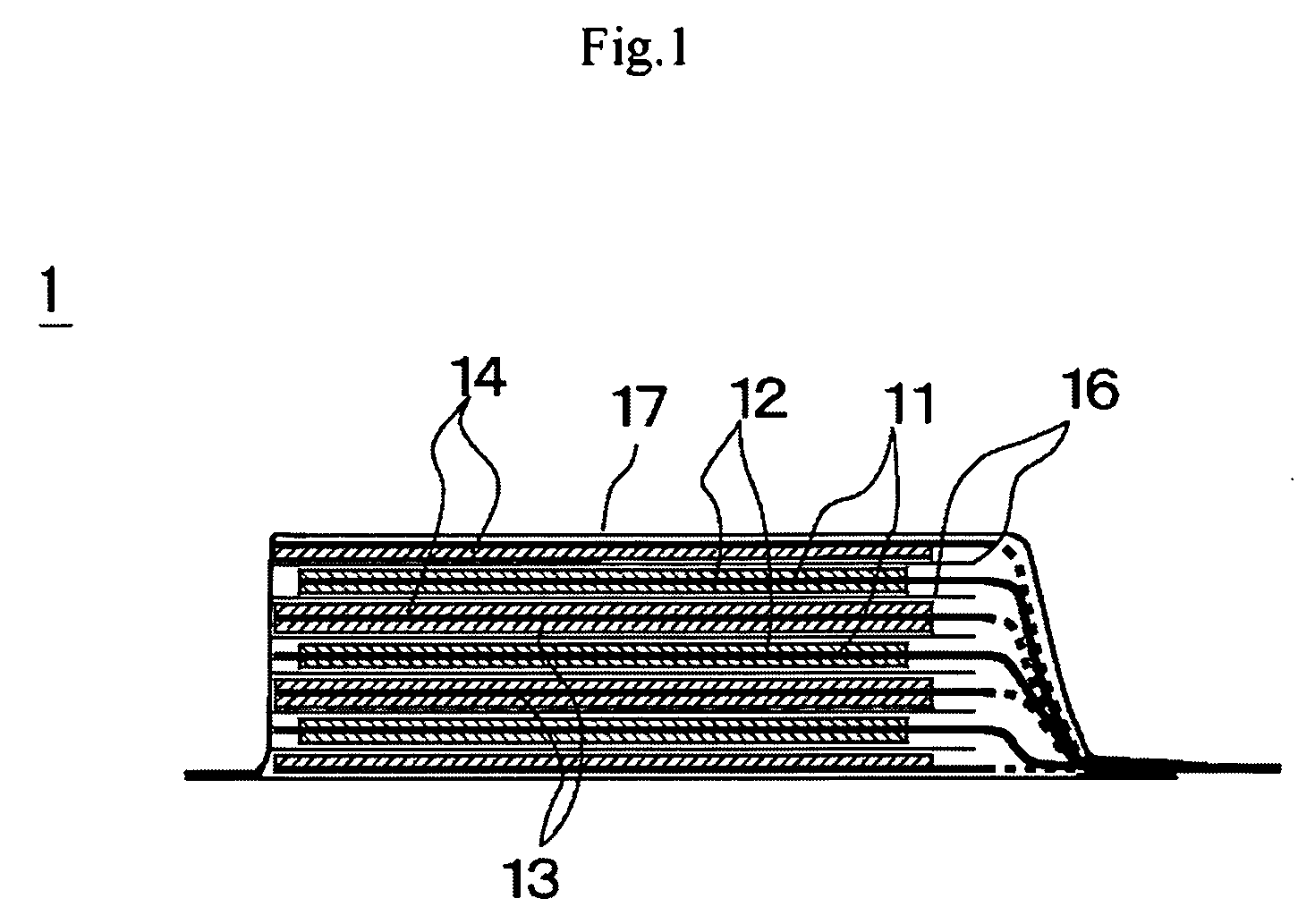
Figure 2 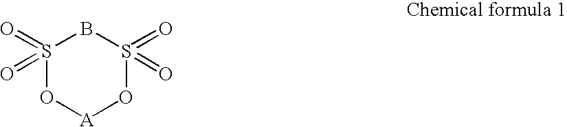
Figure 3
Abstract
Description
CROSS-REFERENCE TO RELATED APPLICATIONS
[0001] This application is based upon and claims the benefit of priority from prior Japanese Patent Application No. 2008-99224, filed Apr. 7, 2008, the entire contents of which are incorporated herein by reference.BACKGROUND OF THE INVENTION
[0002] This invention relates to a non-aqueous electrolyte to be used for secondary batteries and also to a non-aqueous electrolyte secondary battery using the same.
[0003] Non-aqueous electrolyte lithium ions and lithium secondary batteries formed by using a carbon material, an oxide, a lithium alloy or lithium metal for the negative electrode have been attracting attention as power sources for portable telephone sets, notebook type personal computers and so on because they can realize a high energy density. It is known that a film referred to as surface film, protective film or solid electrolyte interface (SEI) or simply as film (to be referred to as “surface film” hereinafter) tends to be formed on the surfac...
Examples
example 1
Preparation of Battery
[0071]Now, the preparation of the battery of this example will be described below. A 20 micrometer-thick aluminum foil was used as positive electrode collector and LiMn2O4 was employed as positive electrode active substance. On the other hand, a 10 micrometer-thick copper foil was used as negative electrode collector and the negative electrode was prepared by depositing lithium metal as negative electrode active substance to a thickness of 20 micrometer on the copper foil by evaporation. A mixture solvent of EC and DEC (volume ratio: 30 / 70) was employed as solvent of electrolyte and LiN(C2F5SO2)2, which is a fluorine-containing organic lithium salt, was dissolved in the mixture solvent as supporting electrolyte by 1 mol / L. Additionally, compound 1 listed in Table 1 shown above was added to the electrolyte so as to be contained by 1 wt %. Then, the negative electrode and the positive electrode were laid one on the other with a polyethylene separator interposed b...
examples 2 , 3 and 4
EXAMPLES 2, 3 AND 4
[0073]Non-aqueous electrolyte secondary batteries were prepared in these examples as in Example 1 except that the compound number 1 was replaced by the respective compounds listed in Table 2 that is, by the compounds of the compound numbers 5, 7, 14 listed in Table 1 and the battery characteristics of these batteries were tested as in Example 1. Table 2 shows the results.
example 5
[0077]A secondary battery was prepared in this example as in Example 1 except that LiN(C2F5SO2)2 was replaced by LiPF6 as supporting electrolyte and the negative electrode was formed by mixing graphite powder, polyvinylidene fluoride dissolved in N-methyl-2-pyrolidone so as to operate as binder and a conductivity providing material into paste, applying the mixture paste to a copper foil and drying it.
[0078]The charge-discharge cycle test of this example was conducted at temperature of 20 degrees C. with a charge rate of 1 C, a discharge rate of 1 C, an end of charge voltage of 4.2V and an end of discharge voltage of 3.0V. The capacity maintenance ratio (%) is the value obtained by dividing the discharge capacity (mAh) after 400 cycles by the discharge capacity (mAh) at the 10th cycle. Table 3 below shows the results obtained from the cycle test.