
Water treatment apparatus
Patent Information
- Authority / Receiving Office
- US · United States
- Current Assignee / Owner
- Publication Date
- 2010-05-06
- Estimated Expiration
- Not applicable · inactive patent
Smart Images
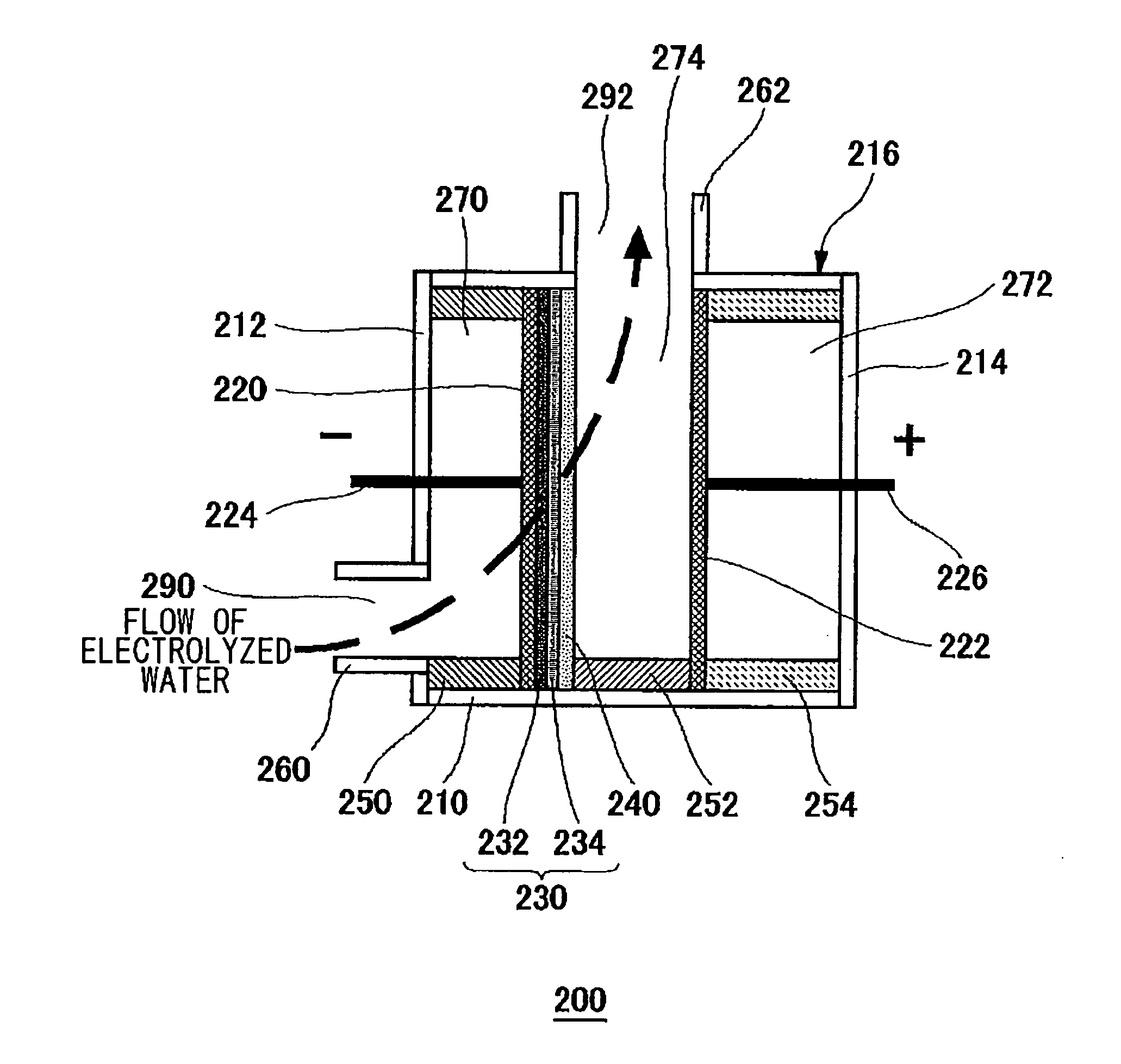
Figure 1 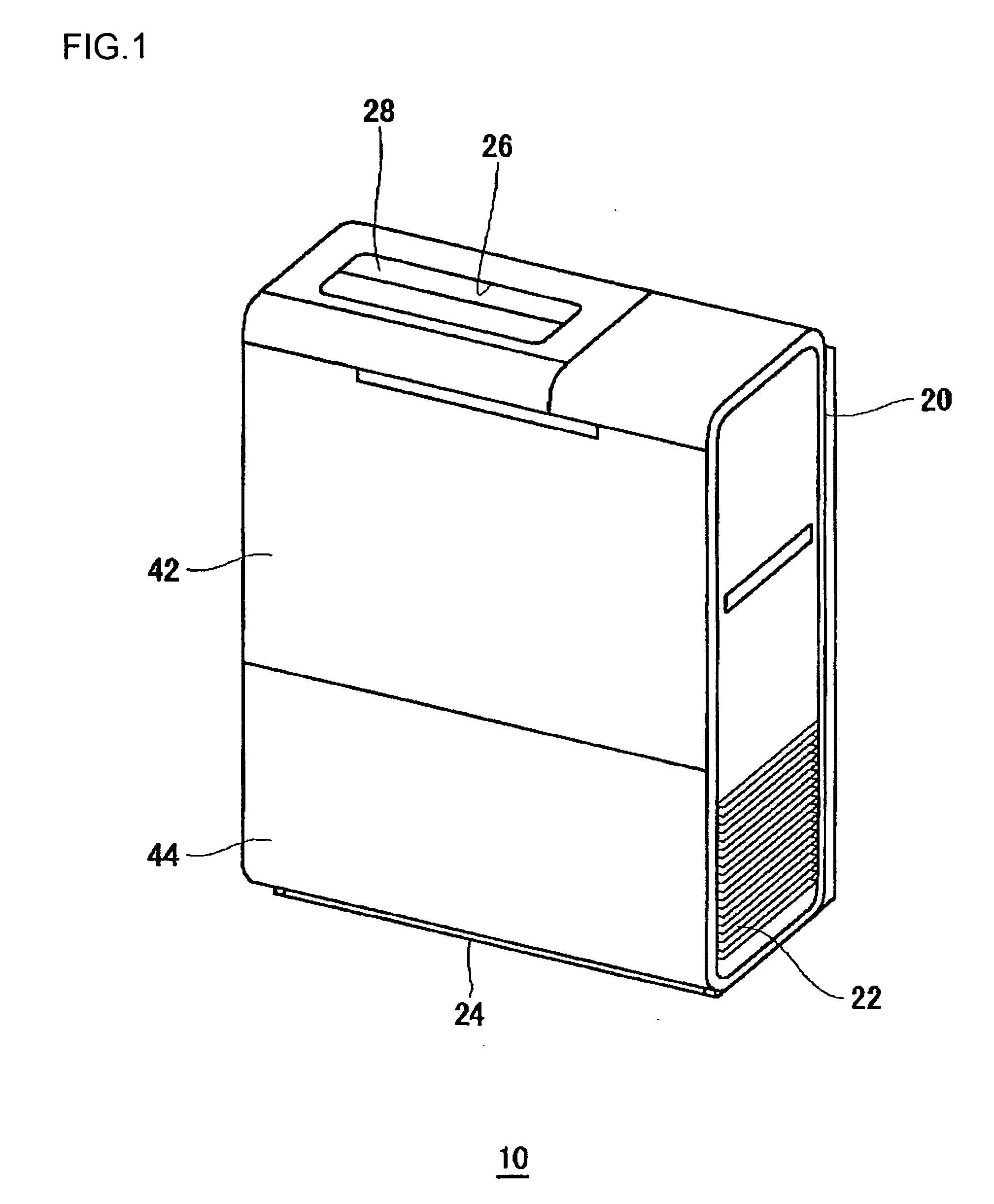
Figure 2 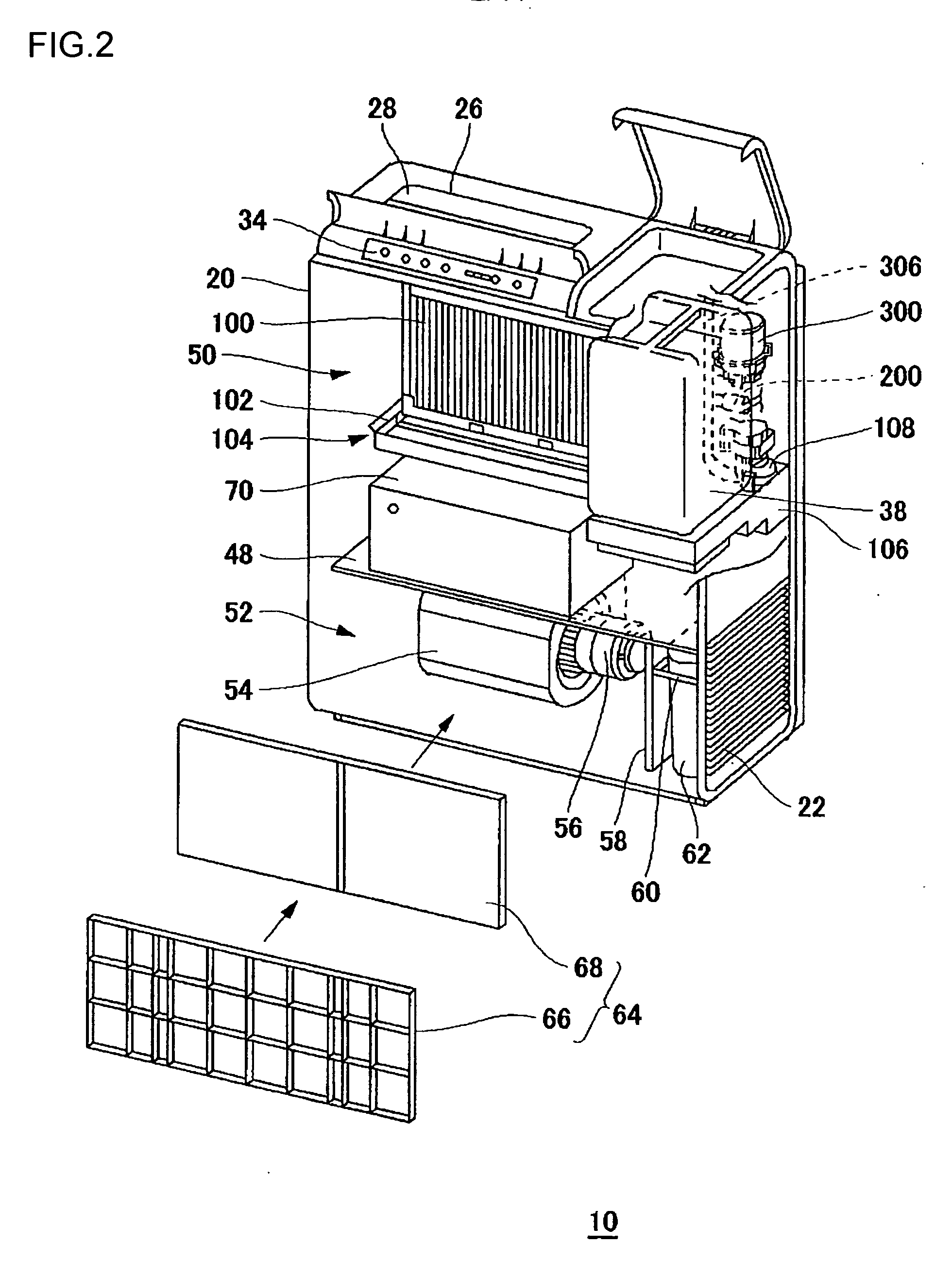
Figure 3
Abstract
Description
CROSS-REFERENCE TO RELATED APPLICATIONS
[0001] This application is based upon and claims the benefit of priority from the prior Japanese Patent Applications No. 2008-255809, filed on Sep. 30, 2008, and Japanese Patent Application No. 2009-069893, filed on Mar. 23, 2009, the entire contents of which are incorporated herein by reference.BACKGROUND OF THE INVENTION
[0002] 1. Field of the Invention
[0003] The present invention relates to a water treatment apparatus that removes hardness components from water electrically.
[0004] 2. Description of the Related Art
[0005] There are air sterilizing apparatuses known in the art which are designed to counteract viruses and the like suspended in the air, using an electrolyzed water, containing hypochlorous acid, generated by an electrolysis of tap water or the like. In this type of air sterilizing apparatus, the air is sterilized as viruses and the like in the air passing through a gas-liquid contact member are inactivated through contact with the elect...
Examples
first embodiment
[0028]FIG. 1 is a perspective illustration of an appearance of an air sterilizing apparatus 10 according to a first embodiment of the present invention. FIG. 2 is a perspective illustration showing an internal structure of the air sterilizing apparatus 10.
[0029]The air sterilizing apparatus 10, which is enclosed in a box-shaped casing 20, is installed on a floor, for instance. The air sterilizing apparatus 10 has air suction grilles 22 formed in the lower part of both side faces of the casing 20. Also, the air sterilizing apparatus 10 has an air suction opening 24 formed in the lower part of the front face of the casing 20.
[0030]The air sterilizing apparatus 10 also has an air blow opening 26 in the upper face of the casing 20, and the air blow opening 26 is provided with a louver 28 which can change the direction of air blowing. The louver 28 has an opening / closing mechanism that can automatically close the air blow opening 26 when the operation is stopped.
[0031]The air sterilizing...
second embodiment
[0106]FIG. 8 is a schematic illustration showing a structure of essential part of an air sterilizing apparatus, where electrolyzed water is generated and circulated, according to a second embodiment of the present invention. FIG. 9 is a schematic illustration of a structure of a water softening module according to the second embodiment. The air sterilizing apparatus 10 according to the second embodiment differs from the first embodiment in the position where the water outlet 292 is disposed and the configuration of the discharge pipe 312. Otherwise, the basic structure of the air sterilizing apparatus 10 according to the second embodiment is similar to that of the air sterilizing apparatus 10 according to the first embodiment. Thus the description of the same structural components as those of the first embodiment will be omitted as appropriate.
[0107]As shown in FIG. 9, in the water softening module 200 incorporated into the air sterilizing apparatus 10 according to the second embodi...
third embodiment
[0109]FIG. 10 is a schematic illustration of a structure of a water softening module according to a third embodiment of the present invention. The basic structure of an air sterilizing apparatus according to the third embodiment is similar to that of the air sterilizing apparatus 10 according to the first embodiment. Thus the description of the same structural components as those of the first embodiment will be omitted as appropriate.
[0110]The water softening module 200 according to the third embodiment includes a pair of electrodes 220 (first electrode) and 222 (second electrode), a conductive filtering medium 231 capable of capturing ions, a support member 240 having insulation properties, and securing rings 250 and 254, which are all housed in a case body 216.
[0111]In the third embodiment, a space (scale precipitation chamber) 274 is formed between the electrode 220 and electrode 222, and a scale collector 275 that communicates with the scale precipitation chamber 274 is formed b...