
Hinge and door unit
a technology for hinges and doors, applied in the field of hinges, to achieve the effect of improving the workability of mounting, reducing the number of mounting bolts, and easy and fine adjustment of a sta
Patent Information
- Authority / Receiving Office
- US · United States
- Patent Type
- Applications(United States)
- Current Assignee / Owner
- Publication Date
- 2011-06-02
- Estimated Expiration
- Not applicable · inactive patent
Smart Images
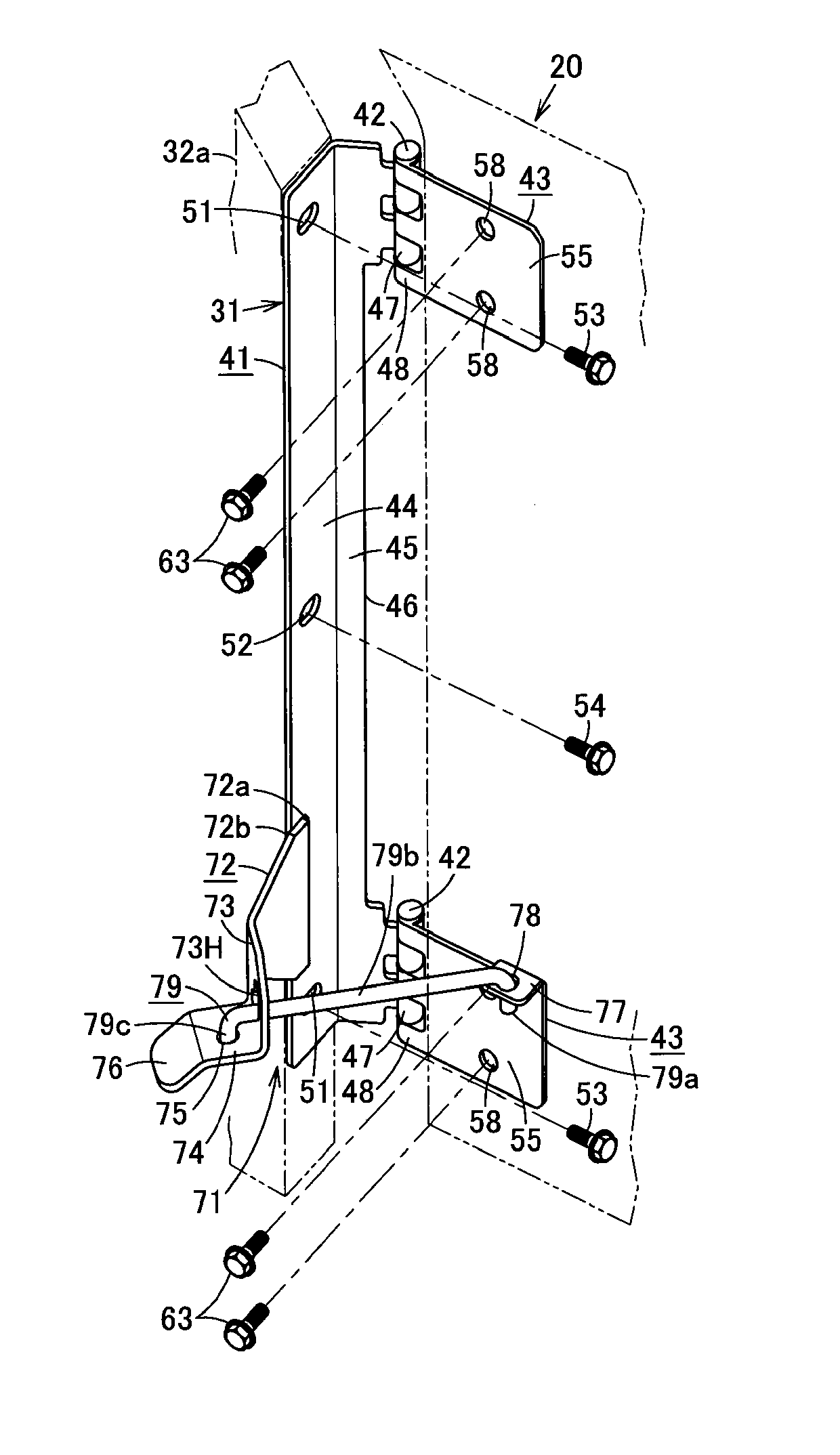
Figure 1 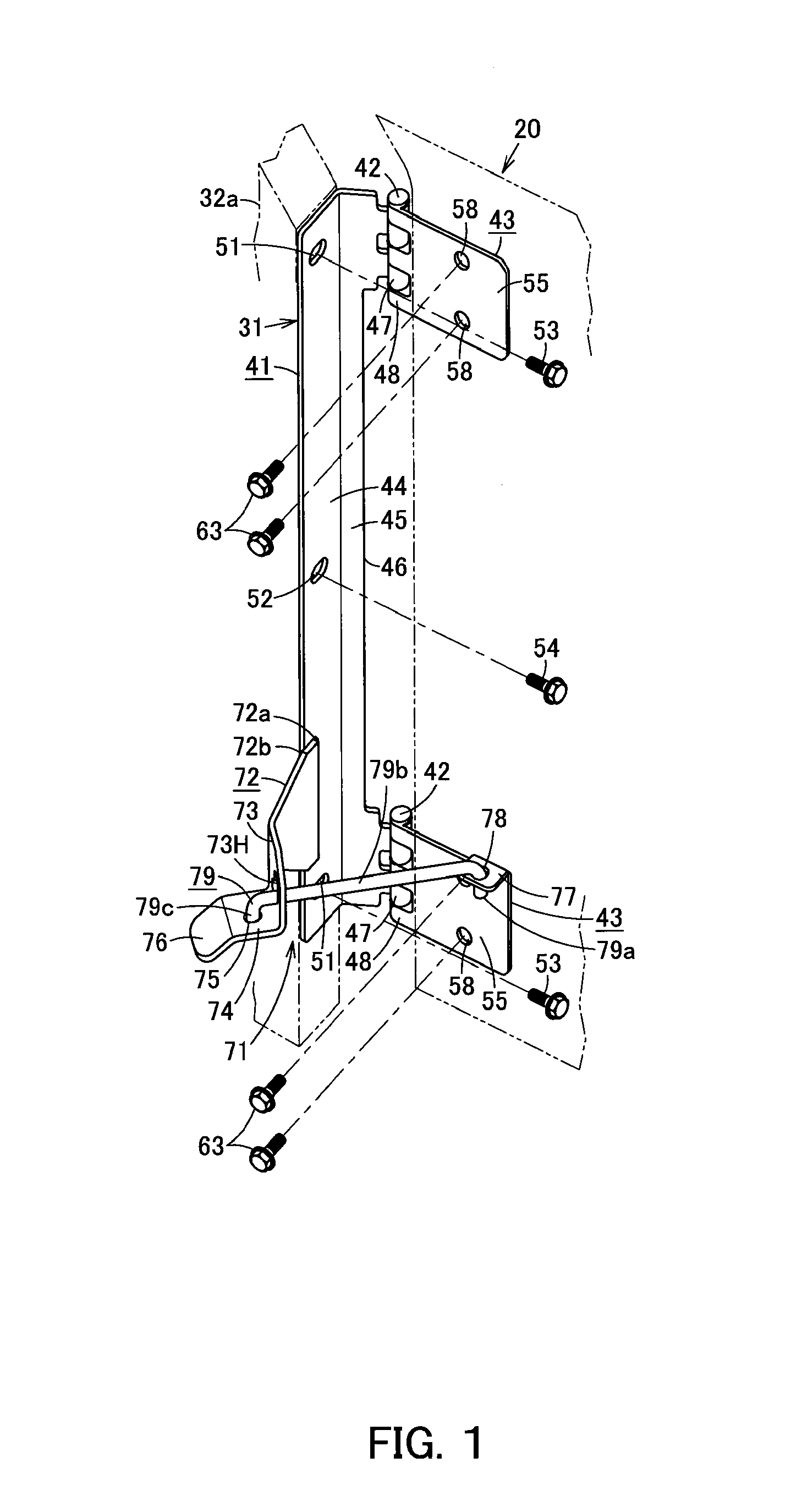
Figure 2 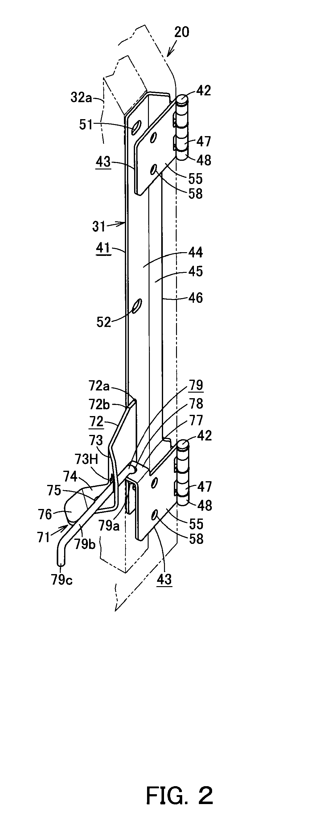
Figure 3
Abstract
Description
CROSS REFERENCE TO PRIOR APPLICATIONS
[0001] This application is a U.S. National Phase application under 35 U.S.C. §371 of International Application No. PCT / JP2009 / 059685, filed on May 27, 2009 and claims benefit of priority to Japanese Patent Application No. 2008-224582, filed on Sep. 2, 2008 and Japanese Patent Application No. 2009-002039, filed on Jan. 7, 2009. The International Application was published in Japanese on Mar. 11, 2010 as WO 2010 / 026806 A1 under PCT Article 21(2). All of these applications are herein incorporated by reference.TECHNICAL FIELD
[0002] The present invention relates to a hinge for mounting a door panel main body to a frame and a door unit which is capable of being opened and closed by the hinge.BACKGROUND OF THE INVENTION
[0003] FIG. 31 illustrates a hydraulic excavator 10, which is a work machine. The hydraulic exactor 10 includes a lower structure 11, an upper structure 12, a cab 13, work equipment 14 and a power system 15 that includes an engine. The cab 13...
Examples
Embodiment Construction
[0065]Hereinafter, the present invention will be described in detail by referring to an example illustrated in FIGS. 1 to 11, another example illustrated in FIGS. 12 to 16, a further example illustrated in FIG. 17, an additional example illustrated in FIGS. 18 to 28, the next example illustrated in FIG. 29, and an example illustrated in FIG. 30.
[0066]First, description will be made for the example illustrated in FIGS. 1 to 11.
[0067]FIG. 7 illustrates a hydraulic excavator 10, which is a work machine. The hydraulic exactor 10 includes a lower structure 11, an upper structure 12, a cab 13, work equipment 14, and a power system 15 that includes an engine. The cab 13, the work equipment 14, and the power system 15 are mounted on the upper structure 12, which is rotatably mounted on the lower structure 11. The power system 15 is covered by a top cover 16, side doors 17 and others.
[0068]As illustrated in FIG. 8, one side of a door panel main body 20 of the side door 17 is mounted to a fra...