
Work vehicle
a technology for working vehicles and vehicles, applied in the field of work vehicles, can solve the problems of degrading the cooling efficiency of the radiator, and achieve the effects of enhancing forward visibility, reducing thermal impact of exhaust gas treatment devices, and sufficient distan
Patent Information
- Authority / Receiving Office
- US · United States
- Patent Type
- Applications(United States)
- Current Assignee / Owner
- Publication Date
- 2012-06-07
Smart Images
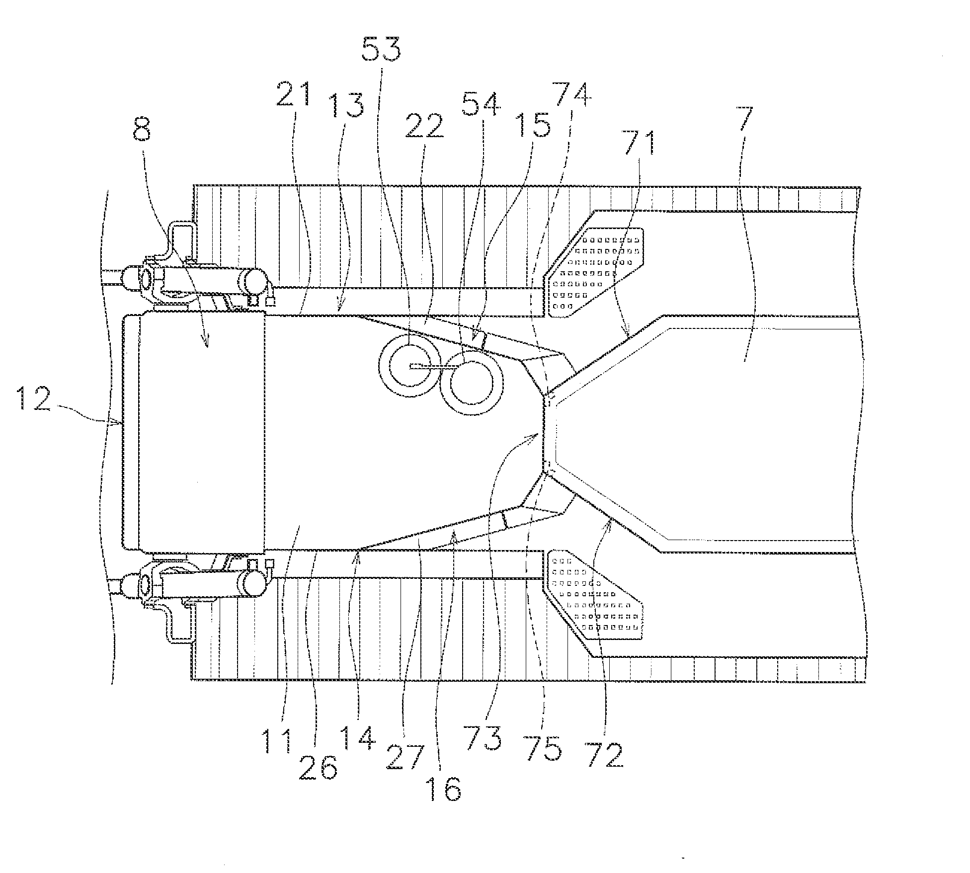
Figure 1 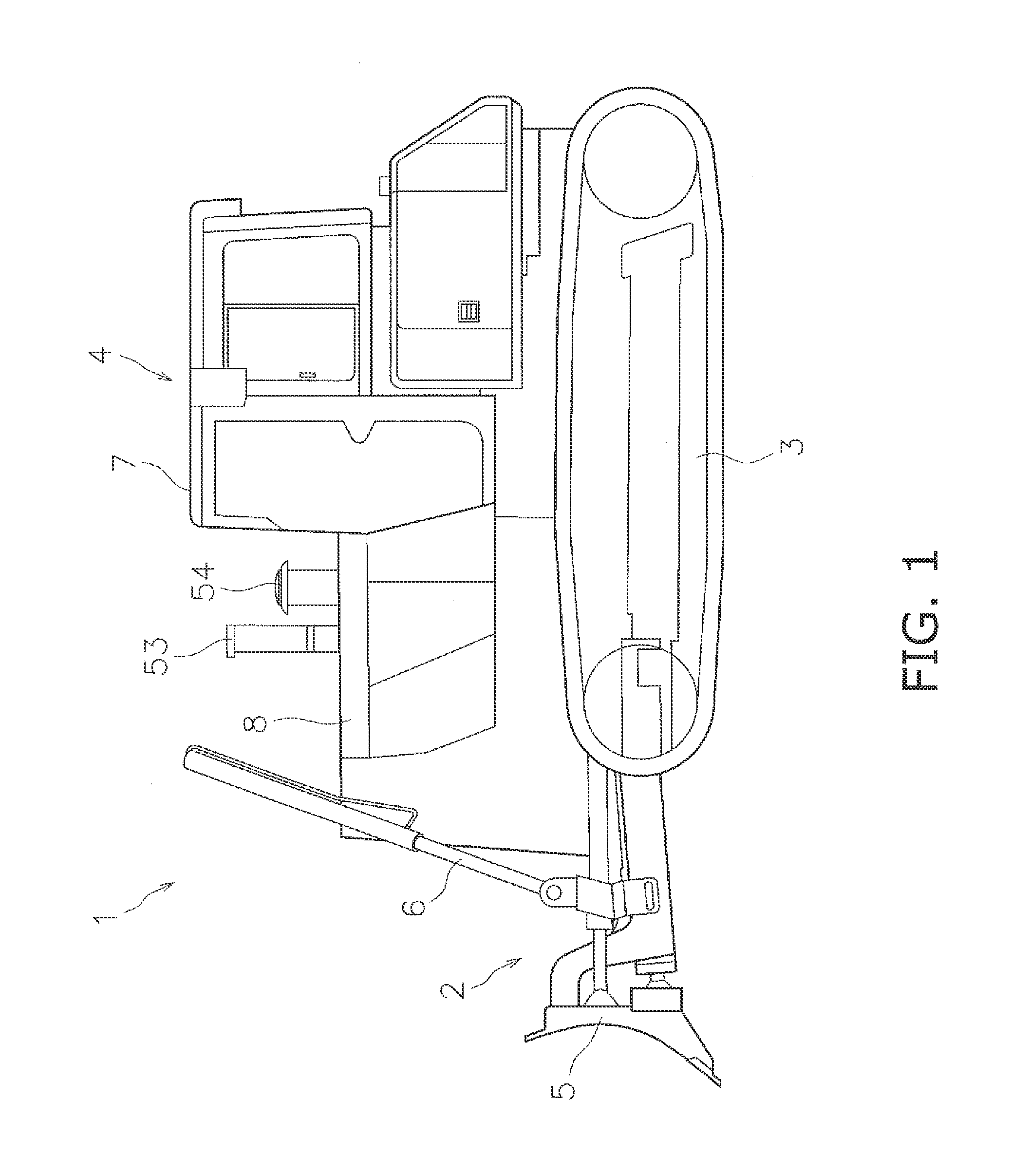
Figure 2 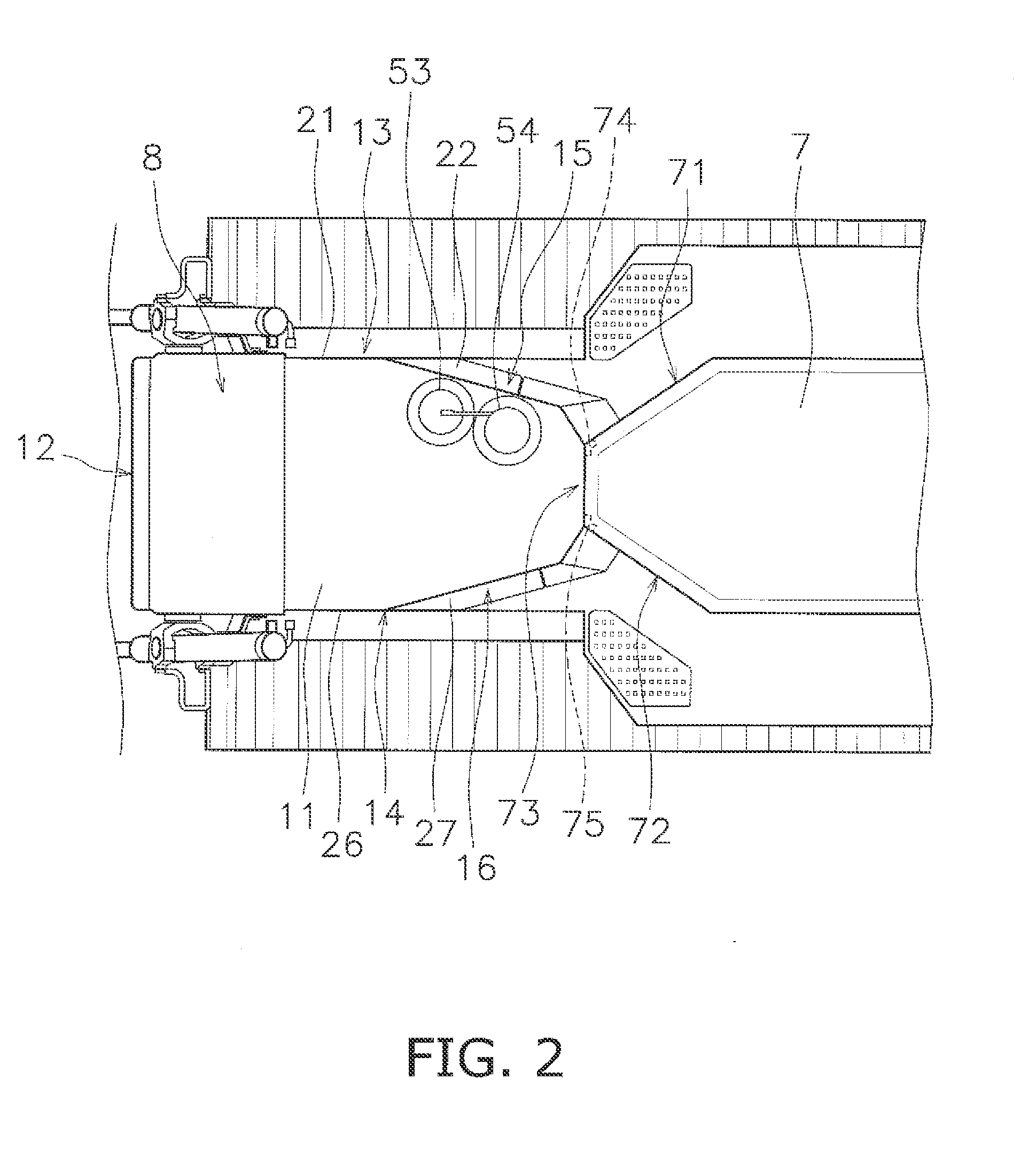
Figure 3
Abstract
Description
CROSS-REFERENCE TO RELATED APPLICATIONS
[0001] This application claims priority to Japanese Patent Application No. 2010-173376 filed on Aug. 2, 2010, the disclosure of which is hereby incorporated herein by reference in its entirety.FIELD OF THE INVENTION
[0002] The present invention related to a work vehicle.BACKGROUND ART
[0003] In some work vehicles, an engine compartment is disposed forwards of a cab. The engine compartment accommodates a variety of devices such as an engine, a radiator, a blower and etc. For instance, an exhaust pipe is connected to the engine through a muffler while being upwardly protruding from the top face of the engine compartment, as described in Japan Laid-open Patent Application Publication No. JP-A-2003-113715. The radiator is disposed forwards of the engine. The blower is configured to generate an airflow passing through the radiator in order to cool down a coolant flowing through the radiator. Further, the engine compartment includes a plurality of vent ho...
Examples
Embodiment Construction
[0028]FIG. 1 illustrates a work vehicle 1 according to an exemplary embodiment of the present invention. The work vehicle 1 is a bulldozer. FIG. 1 is a left side view of the work vehicle 1. It should be noted that the directional terms “right”, “left” and their related terms will hereinafter refer to corresponding directions seen from an operator forwardly directed in a cab 7. The work vehicle 1 includes a work implement 2, a drive unit 3 and a vehicle body 4. The work implement 2 includes a blade 5 and hydraulic cylinders 6. The blade 5 is disposed forwards of the vehicle body 4. The hydraulic cylinders 6 are configured to be driven by means of hydraulic pressure generated by hydraulic pumps (not illustrated in the figure) and move the blade 5 up and down. The drive unit 3 is a track-type drive unit attached to the vehicle body 4. The vehicle body 4 includes the cab 7 and an engine compartment 8.
[0029]The cab 7 is embedded with a seat and an operating device (not illustrated in the...