
Method of operating polymer electrolyte fuel cell
a fuel cell and electrolyte technology, applied in the direction of solid electrolyte fuel cells, fuel cells, cell components, etc., can solve the problems of inability to form a char layer under the above conditions, small improvement of output density, and unclear effectiveness of rod-shaped minute protrusions, etc., to achieve high electric power generation performance, performance deterioration, and surface area increase
Patent Information
- Authority / Receiving Office
- US · United States
- Patent Type
- Applications(United States)
- Current Assignee / Owner
- Publication Date
- 2012-07-26
- Estimated Expiration
- Not applicable · inactive patent
Smart Images
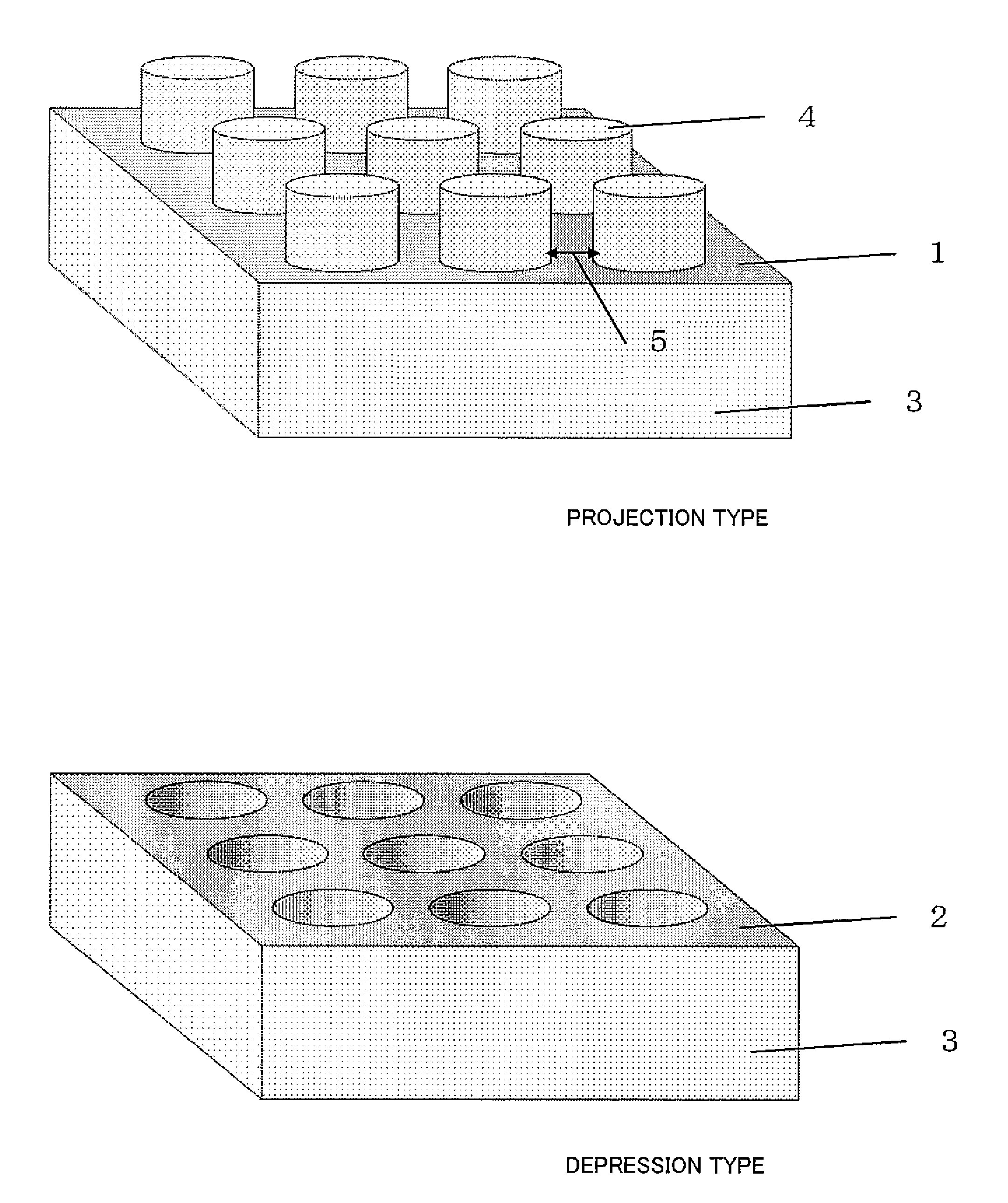
Figure 1 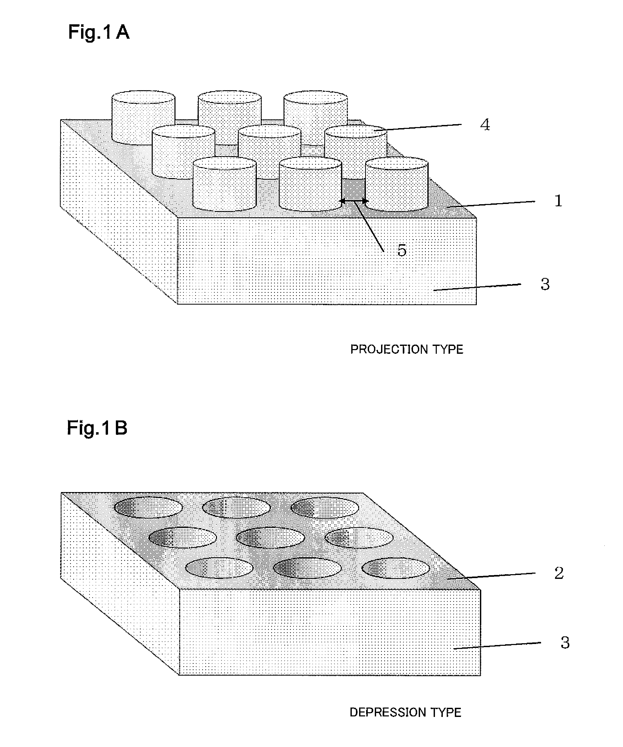
Figure 2 
Figure 3
Abstract
Description
[0001] This is a continuation application under 35 U.S.C 111(a) of pending prior International application No. PCT / JP2010 / 003930, filed on Jun. 14, 2010.BACKGROUND OF THE INVENTION
[0002] 1. Field of the Invention
[0003] The present invention relates to an electric power generating method of a polymer electrolyte fuel cell which can be used as an electric car power supply or a domestic power supply system and uses hydrogen or hydrocarbon, such as alcohol, as fuel.
[0004] 2. Description of the Related Art
[0005] To improve the performance of a polymer electrolyte fuel cell, a method has been reported, in which: projections and depressions are formed on the surface of an electrolyte membrane to increase a contact area between a catalyst layer and the electrolyte membrane. Japanese Laid-Open Patent Application Publication No. 2005-108822 discloses a method in which a projection-depression structure is formed on the surface of the electrolyte membrane by pressing against the surface of the elect...
Examples
embodiment 1
[0032]FIGS. 1A and 1B are conceptual diagrams each showing the surface of an electrolyte membrane including a depression-projection structure in the present invention. As shown in FIG. 1A, a structure in which a flat lower base portion 1 is continuously formed and a plurality of discontinuous protrusions (projections) are formed on the flat lower base portion 1 is called a projection type in the present invention. As shown in FIG. 1B, a structure in which a flat upper base portion 2 is continuously formed and a plurality of discontinuous holes (depressions) are formed on the flat upper base portion 2 is called a depression type in the present invention. FIGS. 1A and 1B show columnar projections and depressions as a representative example. However, the shape of each of the projections and depressions may be a polygonal column, such as a quadrangular prism or a triangular prism. In addition, the shape may be a cone or a pyramid. Various shapes are applicable to the projections and dep...
example 1
[0045]A projection type electrolyte membrane was produced by the casting of a fluoropolymer electrolyte solution by using a depression type mold. The depression type mold was produced by: forming various patterns on a silicon wafer by masks; and performing plasma etching. The cross-sectional shape of the projection and the projection-projection interval were adjusted by a mask pattern, and the height of the projection was adjusted by the time and intensity of the plasma etching. Used as the polymer electrolyte solution was a Nafion liquid (water / alcohol solvent, solid content ratio was adjusted to about 20%). The silicon wafer on which the projections of various shapes and the depressions of various shapes were formed was coated with the Nafion liquid and was then dried. When drying, the temperature and humidification conditions of the atmosphere were adjusted. According to need, the Nafion liquid coating and the drying were repeatedly performed plural times. After the drying, a hea...
example 2
[0063]In Example 1, the current-voltage characteristics of the small cells each including the projection type electrolyte membrane were evaluated. In Example 2, the current-voltage characteristics of the small cells each including the depression type electrolyte membrane were evaluated. In this depression type electrolyte membrane, the diameter of the depression was set to 10 μm. A depression-depression interval, that is, a rib width was set to 5 μm that was the same as the diameter (φ) of the projection of the projection type membrane, and the depth of the depression was set to 10 or 15 μm that was the same as the height of the projection of the projection type membrane. The other components, such as the catalyst layer and the gas diffusion layer, were the same as those of the small cell including the projection type membrane in Example 1. Thus, the small cell was produced, and the current-voltage characteristics thereof were evaluated.
[0064]FIG. 7 shows the current-voltage charact...