
System and methods for engine air path condensation management
Patent Information
- Authority / Receiving Office
- US · United States
- Current Assignee / Owner
- Publication Date
- 2015-06-25
- Estimated Expiration
- Not applicable · inactive patent
Smart Images
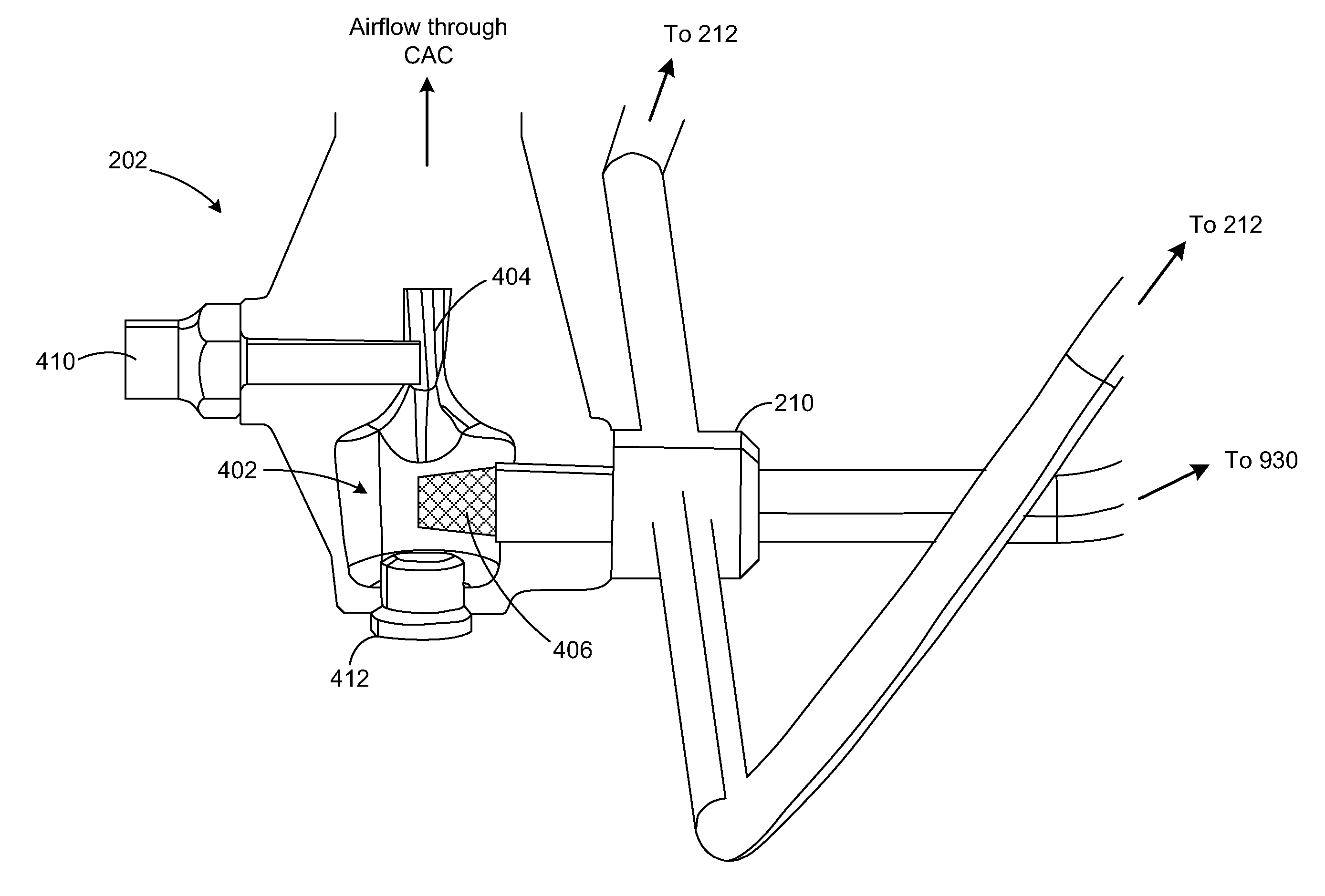
Figure 1 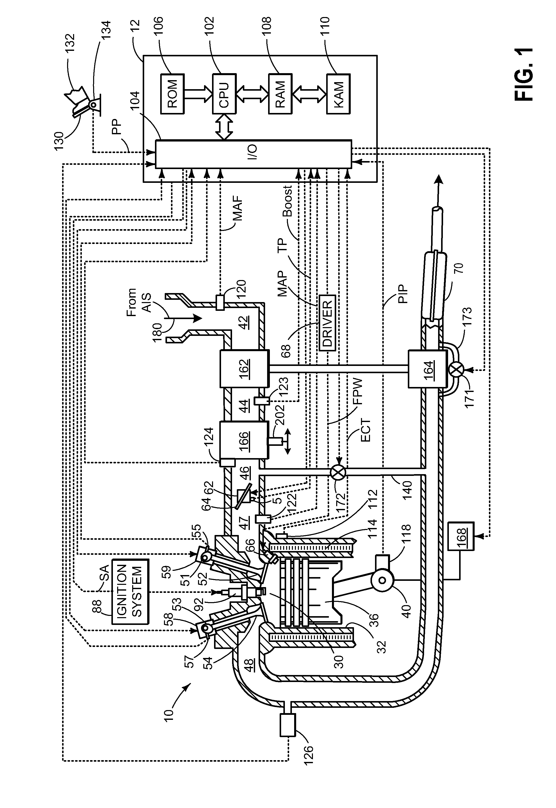
Figure 2 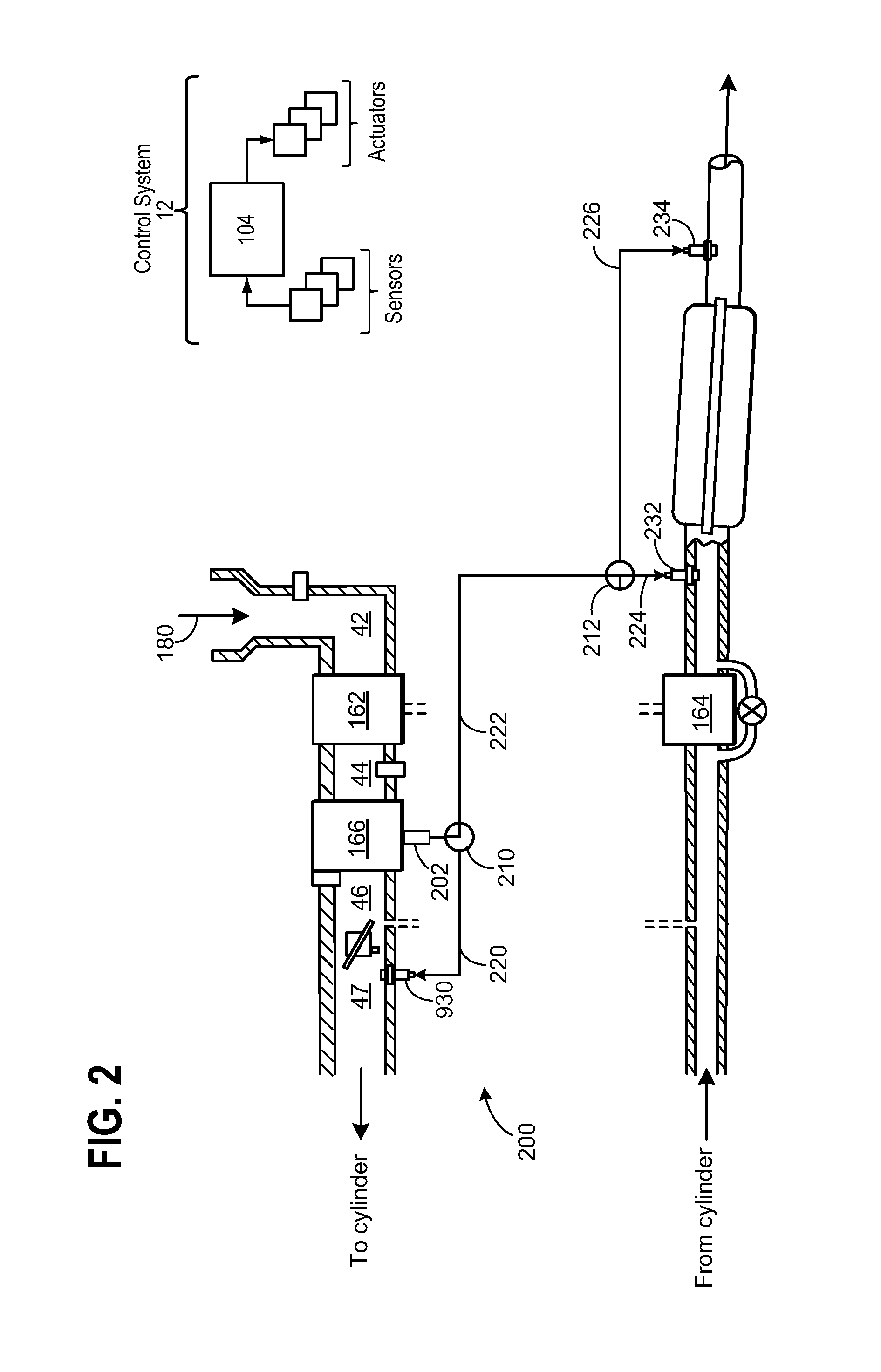
Figure 3
Abstract
Description
FIELD
[0001] The field of the disclosure relates to detection of contaminants in condensate, formed naturally, and collected in a Charge Air Cooler coupled to an engine intake air path and / or exhaust air path whereby actions are taken in response to the detection.BACKGROUND AND SUMMARY
[0002] Boosted engines are in common use in which air is compressed by an air compressor powered by either a turbo positioned in the engine exhaust or powered by the engine crankshaft. Compression will increase air temperature. Consequently the compressed air is often routed through a heat exchanger commonly referred to as a charge air cooler before entering the engine air intake system. Under high ambient air humidity conditions condensate will form in the heat exchanger. In some prior approaches condensate is always routed into the engine exhaust and in other prior approaches condensate is always routed into the engine air intake.
[0003] The inventors herein have recognized that always routing the condens...
Examples
second embodiment
[0067]Condensate collected at the bottom of CAC 166, may then be re-introduced to the engine system at one of three position based on the type of contaminate sensed in the condensate. As mentioned above, the condensation management system further includes accumulator 902 for storing pressurized air. Thus, the method comprises routing air from a compressor through a heat exchanger to a combustion chamber of the engine; coupling condensate formed in the heat exchanger through a passage coupled to the combustion chamber; accumulating a portion of the compressed air in an accumulator; and when the engine output is below a predetermined amount, coupling a part of the accumulated air through the passage into the combustion chamber, wherein said compressor is driven by a turbo positioned in the engine exhaust, or by a mechanical coupling to a crankshaft or a camshaft of the engine.
[0068]As shown in the example of FIG. 9, accumulator 902 is coupled to the condensation management system in ...
third embodiment
[0083]In the inline engine the collection area is located within intake manifold 47. Therefore, condensate is collected in condensate reservoir 1502 that is re-located to the lowest point within intake manifold 47. As such air that enters CAC inlet tank 42 may be cooled as it flows through CAC 1566, which is shown as a water to air charge air cooler. Then, as the airflow continues through intake manifold 47, condensate may collect at reservoir 1502. As described above, reservoir 1502 may be configured to include inlet tank assembly 202 for routing said collected condensate throughout engine 10 in the manner already described. In addition, accumulator 902 may be reconfigured based on the structure of the engine and intake system. For example, FIG. 15, shows accumulator inlet 910 in communication with CAC 1566 outlet tank 45. Therefore, airflow within the system may be directed to the auxiliary canister to increase the stored boost pressure within accumulator 902 in the same manner d...