
Rotary ram-in compressor
a compressor and ram technology, applied in the direction of liquid fuel engines, marine propulsion, vessel construction, etc., can solve the problems of the practical useful range of operating rotational speed, the conventional type of positive displacement compressor is not convenient for use in gas turbine engines,
Patent Information
- Authority / Receiving Office
- US · United States
- Patent Type
- Patents(United States)
- Current Assignee / Owner
- Publication Date
- 2005-04-12
- Estimated Expiration
- Not applicable · inactive patent
Smart Images
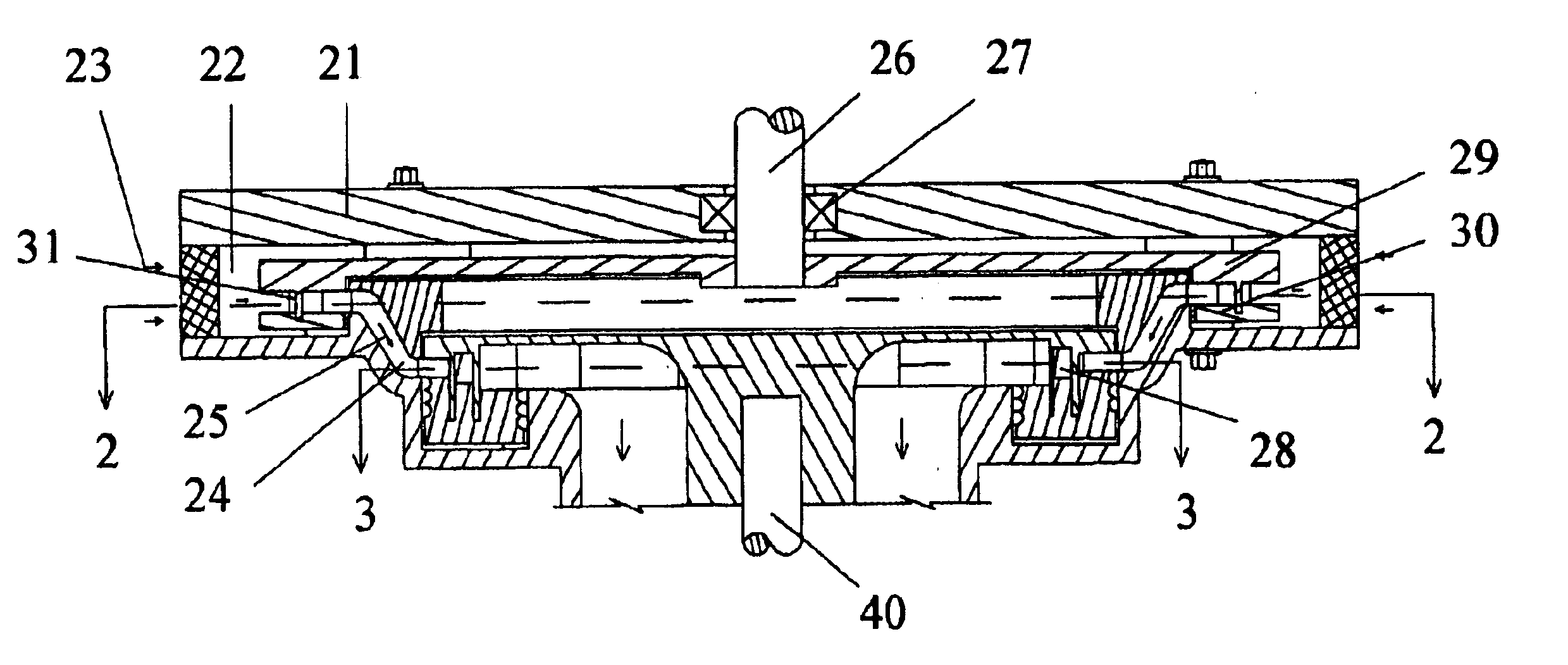
Figure 1 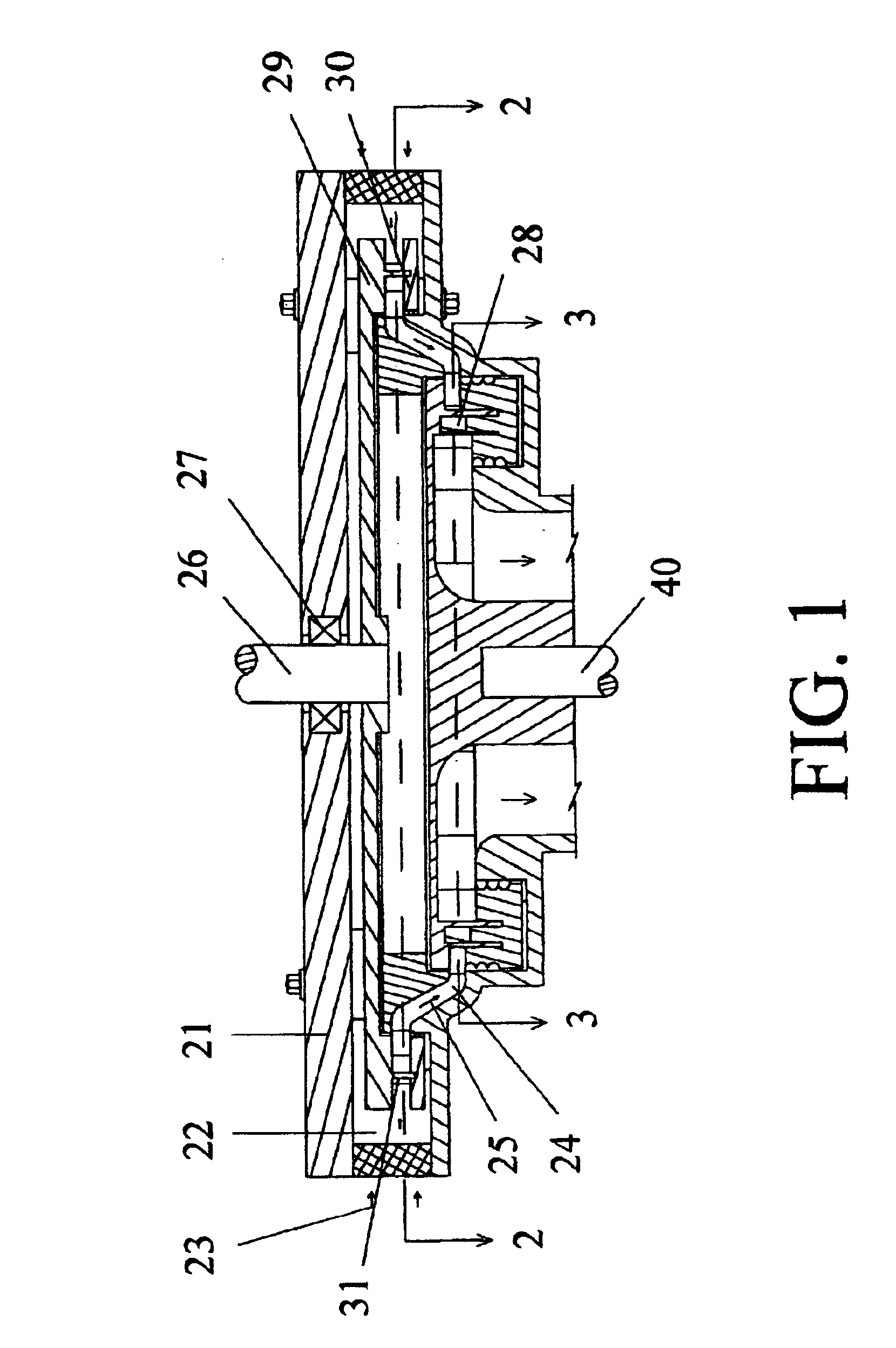
Figure 2 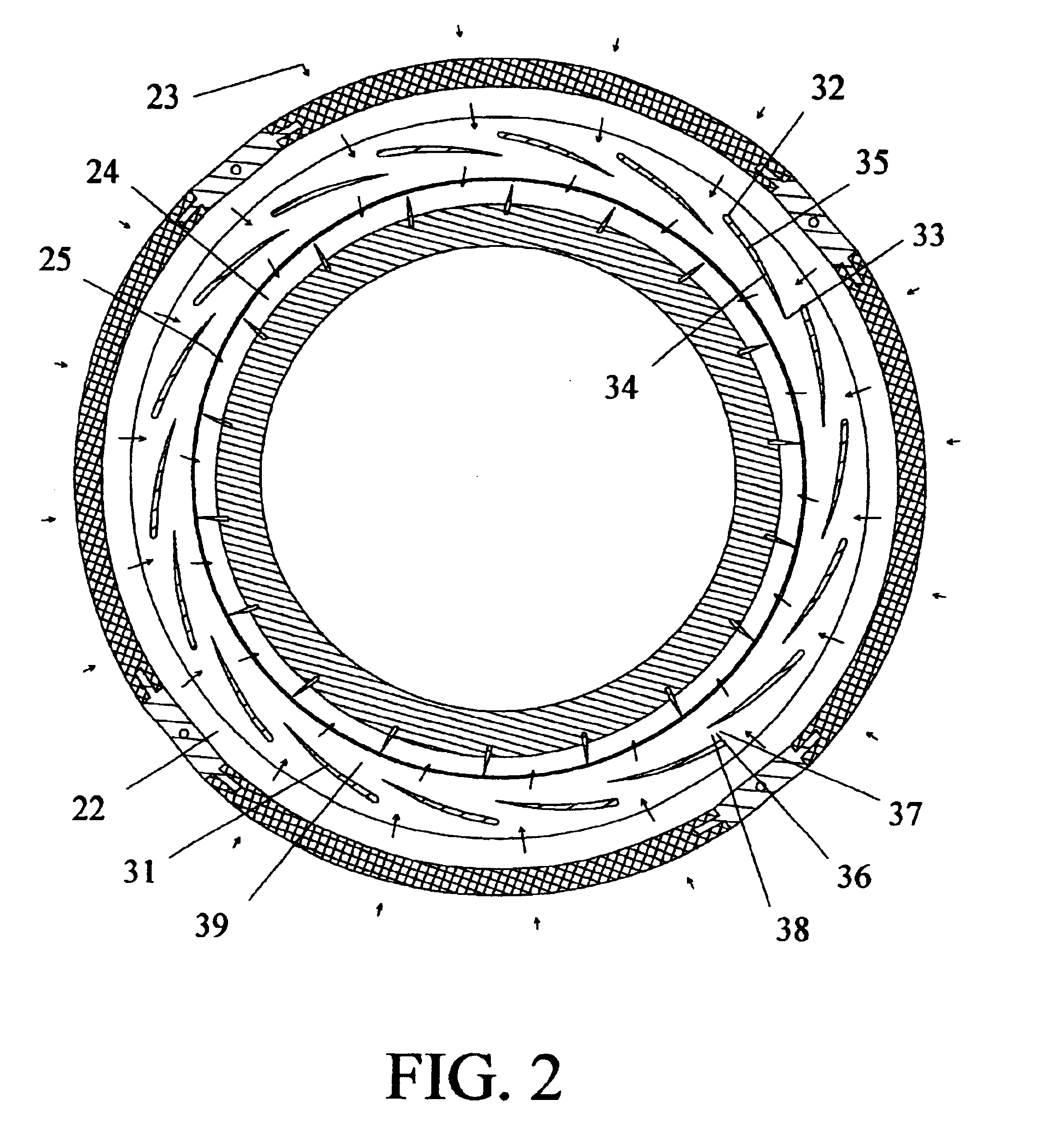
Figure 3
Abstract
Description
FIELD OF THE INVENTIONThe present invention relates to a positive displacement compressor and, more particularly, to a rotary positive displacement compressor convenient for use in gas turbine engines and the like.DESCRIPTION OF PRIOR ARTRotary compressors are well known devices, used in several fields to develop a pressure gradient between two points across a stream of working gases. Two main types of rotary compressors are in use, dynamic compressors, i.e., centrifugal flowing, axial flowing, and the combined types, and positive displacement compressors. In dynamic compressors the working gases are accelerated followed by its deceleration within diverging passages, wherein part of its kinetic energy is converted into static pressure rise. In positive displacement compressors the pressure is increased by reducing the specific volume of the gases during their passage through the compressor.Dynamic Compressors are widely in use in gas turbine and steam engines as they are able to rai...
Examples
Embodiment Construction
FIG. 1 is a sectional view in a schematic representation of an exemplary embodiment of a rotary ram-in compressor, in accordance with the present invention.
The main components of the rotary ram-in compressor in this embodiment are a stationary casing (21) having an inlet passage (22) for admission of working gases (23), and a receiver (24) wherein pressurized gases (25) collect; a drive shaft (26) supported for rotation in a given direction inside the casing by an arrangement of bearings (27), and extending to a drive receiving end located outside the casing; and a rotor assembly housed inside the casing and secured for rotation with the drive shaft (26). The rotor assembly comprises a first disk (29) secured for rotation with the drive shaft (26) and lying in a first plane transverse to the rotational axis of the drive shaft; a second disk (30) having a large open center and a widened rim, and lying in a second plane transverse to the rotational axis of the drive shaft, with the in...