
Controlled radial magnetic bearing
a magnetic bearing and control technology, applied in the direction of magnetic bearings, mechanical energy handling, mechanical equipment, etc., to achieve the effect of small rotation loss, small eddy current loss, and reduced eddy curren
Patent Information
- Authority / Receiving Office
- US · United States
- Patent Type
- Patents(United States)
- Current Assignee / Owner
- Publication Date
- 2005-04-26
- Estimated Expiration
- Not applicable · inactive patent
Smart Images
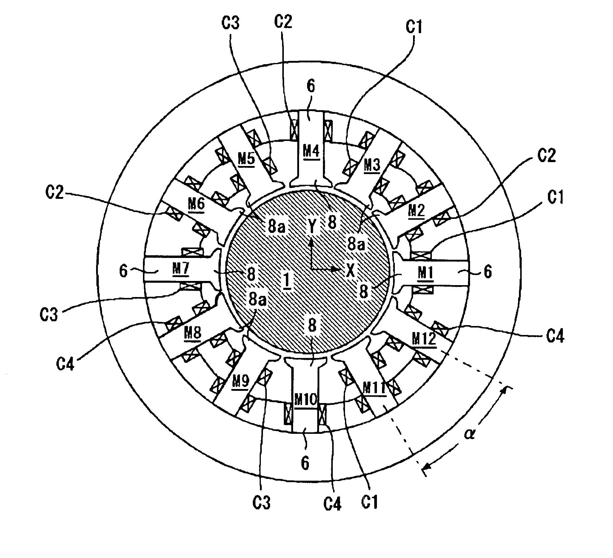
Figure 1 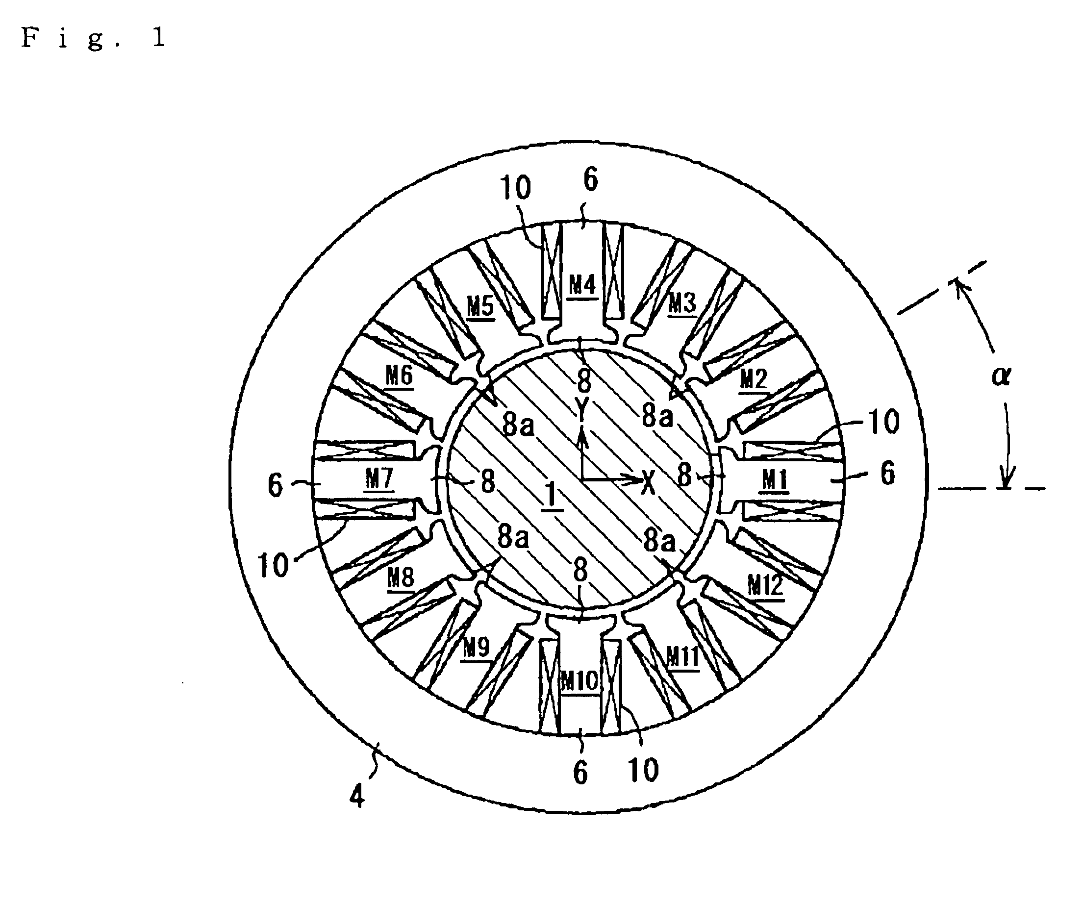
Figure 2 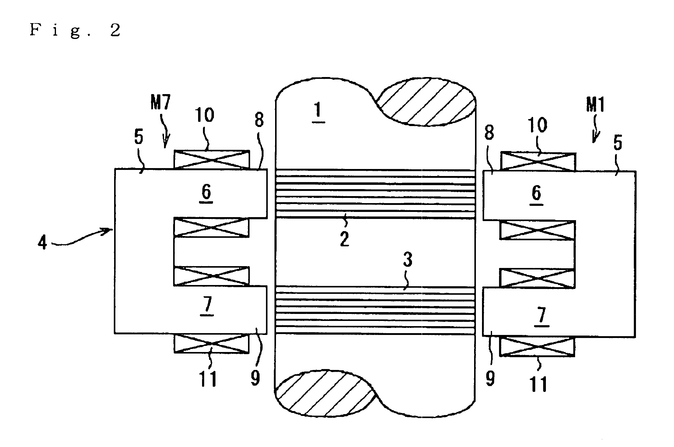
Figure 3
Abstract
Description
TECHNICAL FIELD TO WHICH THE INVENTION RELATES
[0001] This invention relates to a controlled type magnetic radial bearing which supports a rotary body used for an energy-storage flywheel, an ultra high-speed rotating body or the like in a non-contact manner in a radial direction.BACKGROUND ART
[0002] Controlled type magnetic bearing devices, which magnetically levitate a rotary body for supporting in a non-contact state, have been widely used in various fields in recent years since the loss accompanied by rotation can be remarkably reduced.
[0003] Generally a controlled type magnetic bearing device is provided with a group of controlled type magnetic axial bearings which support a rotary body in a non-contact state in an axial direction and two groups of controlled type magnetic radial bearings which support the rotary body in a non-contact state in a radial direction. The magnetic radial bearing is equipped with plural electromagnets (usually four pieces) which are arranged at equal inte...
Examples
first embodiment
[0054]Next, with reference to FIG. 3, a control system for the magnetic radial bearing will be described. In FIG. 3, only the portions of the rotary body 1 and the magnetic pole 6 of the respective electromagnets M are shown.
[0055]Although detailed illustration is omitted, two x-axis-direction position sensors 12 and 13 for detecting displacement of the rotary body 1 in the x-axis direction and two y-axis-direction position sensors 14 and 15 for detecting displacement of the rotary body 1 in the y-axis direction are provided near the electromagnets M.
[0056]A controller (control means) 16 for radial direction control which controls the exciting current supplied to the coils 10 and 11 of the respective electromagnets M based on the output signal from the position sensors 12 to 15 is provided in the magnetic radial bearing. The controller 16 is provided with an x-axis-direction displacement calculating section 17 for determining a displacement of the rotary body 1 in the x-axis direct...
second embodiment
[0072]The upper magnetic radial bearing 23 is provided with twelve electromagnets (upper electromagnets) m1 to m12 arranged in a similar manner as the second embodiment described above. Each of the electromagnets “m” is equipped with a salient pole 8, around which a coil 10 is wound so as to constitute a magnetic pole 6. Each of the salient poles 8 is opposed to the outer peripheral face of an upper rotor part 2 of the rotary body 1. The lower magnetic radial bearing 24 is equipped with twelve electromagnets (lower electromagnets) m1 to m12 arranged in the similar manner as the upper electromagnets “m”. In FIG. 6, only two lower electromagnets m1 and m7 are shown. The lower electromagnets are shown generically with a notational symbol “m”. The constitution of the lower electromagnets “m” is the same as the upper electromagnets “m” and the same notational symbol is given to the same portion.
[0073]The salient pole 8 of the lower electromagnet “m” is opposed to the outer peripheral fac...
fifth embodiment
[0096]A constitution of the controller 16 is similar to the fifth embodiment except for the number of amplifiers A and a part of processing in the control section 19. The controller 16 is provided with two amplifiers A1 and A2 corresponding respectively to two groups of coils C.
[0097]In the controller 16, as similar to the second embodiment, a control section 19 calculates a control current value Ixc in an X-axis direction and a control current value Iyc in a Y-axis direction and outputs control current value signals proportional to these control current values Ixc and Iyc to the corresponding amplifiers A. The control current Ixc is supplied to the first coil C1 from the first amplifier A1 and the control current Iyc is supplied to the second coil C2 from the second amplifier A2. Thereby the control current Ixc is supplied to the first coil 1 of the first to the third electromagnets M1 to M3, the eleventh and the twelfth electromagnets M11 and M12. On the other hand, the control cu...