
Zero-voltage-switched, full-bridge, phase-shifted DC-DC converter with improved light/no-load operation
Patent Information
- Authority / Receiving Office
- US · United States
- Current Assignee / Owner
- Publication Date
- 2005-06-21
- Estimated Expiration
- Not applicable · inactive patent
Smart Images
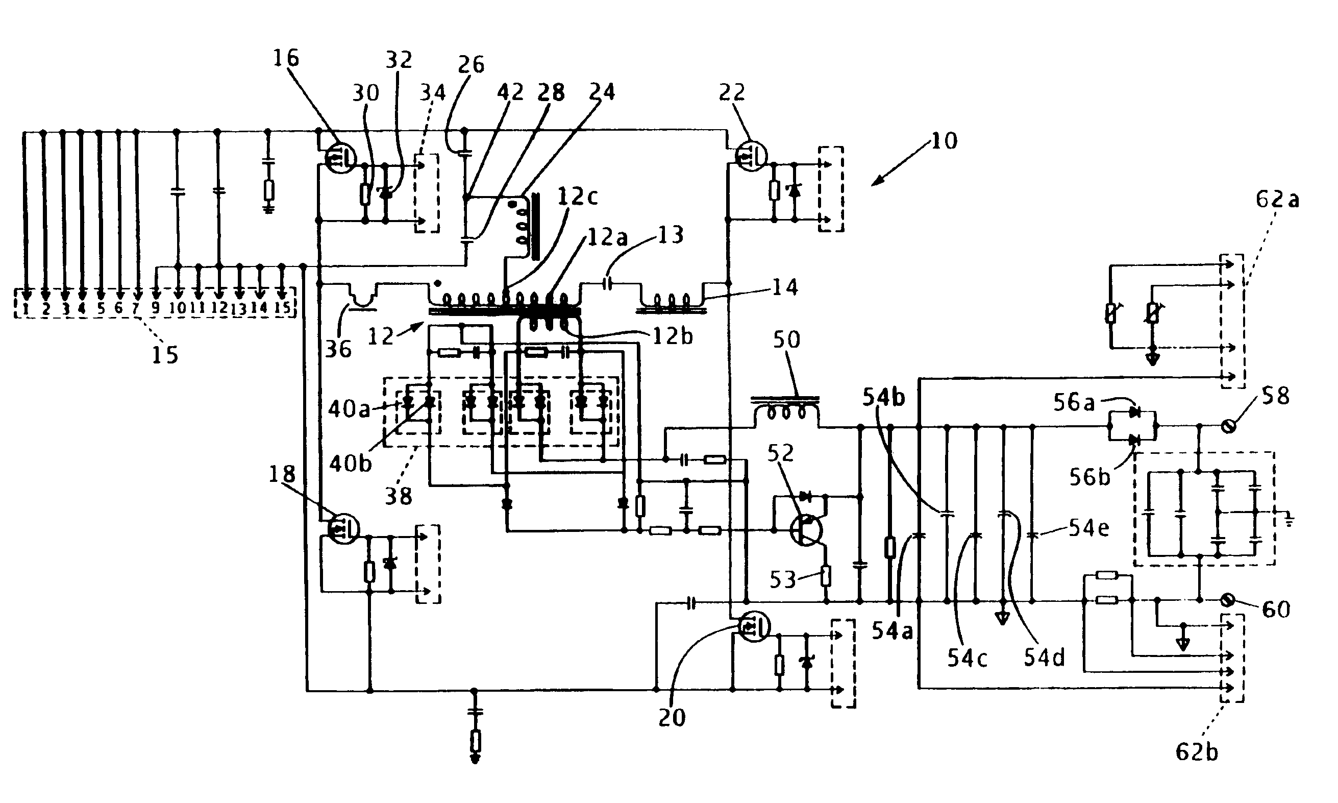
Figure 1 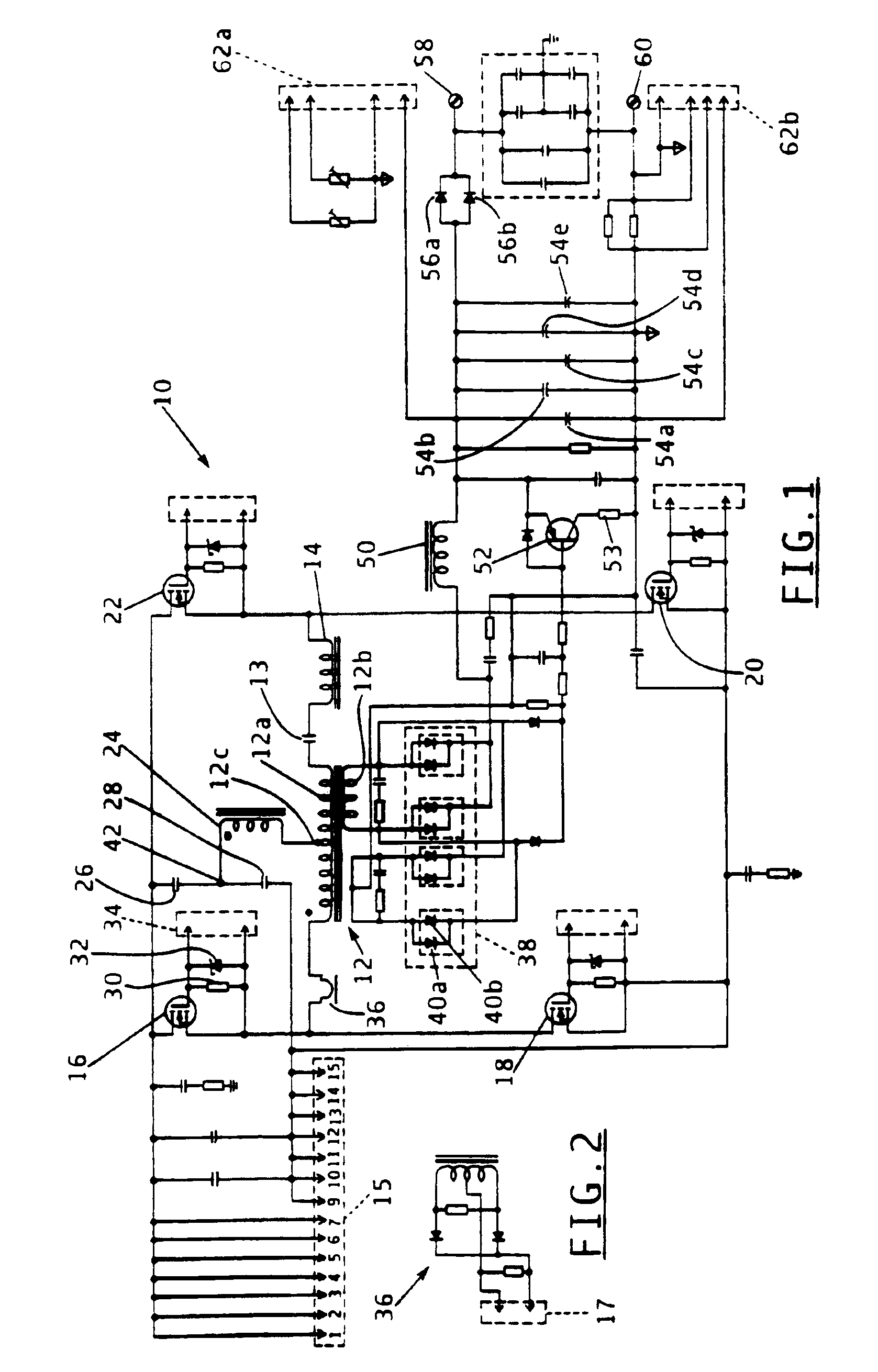
Figure 2 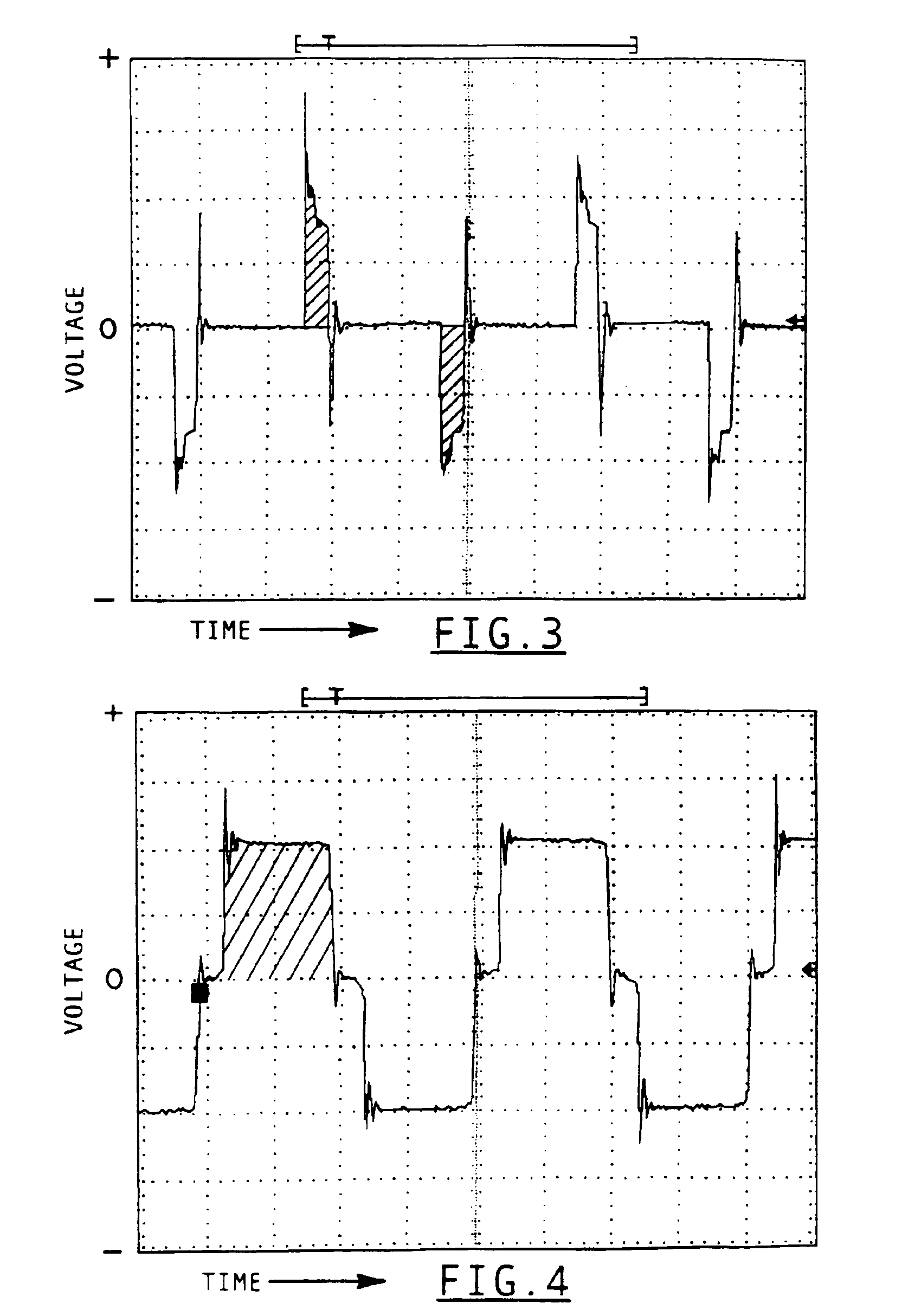
Figure 3
Abstract
Description
FIELD OF THE INVENTION
[0001] This invention relates generally to DC power supplies or battery chargers and is particularly directed to an arrangement for increasing the operating efficiency of a zero-voltage-switched, full-bridge, phase-shifted DC-DC converter such as used in a DC power supply or a battery charger.BACKGROUND OF THE INVENTION
[0002] Zero-voltage-switched (ZVS), full-bridge (FB), phase-shifted (PS) converters are commonly used for DC-DC conversion because of the several advantages that they offer over other approaches. These advantages include high efficiency, i.e., reduced duty cycle loss, due to zero-voltage-switching, or “soft” switching, a relatively small circulating energy, and constant frequency operation allowing for simple control of the converter. DC-DC converters of this type are typically incorporated in a wide range of DC power supplies having various applications such as in battery chargers.
[0003] One disadvantage of the conventional ZVS-FB-PS converter is t...
Examples
Embodiment Construction
[0018]Referring to FIG. 1, there is shown a schematic diagram of a zero-voltage-switched, full-bridge, phase-shifted DC-DC converter 10 with light load or no-load operating conditions compensation in accordance with the principles of the present invention. The inventive DC-DC converter 10 is intended for use in a DC power supply where a DC input voltage is converted to a regulated DC output voltage. These types of DC power supplies are used in various applications such as in battery chargers, telecommunications systems, motor drives, etc.
[0019]DC-DC converter 10 includes a power, or voltage, transformer 12 having a primary winding 12a and a secondary winding 12b. An input current is provided to the power transformer's primary winding 12a through the primary of a current transformer 36, which is shown in greater detail in the schematic diagram of FIG. 2. Connector 17 of the current transformer 36 secondary shown in FIG. 2 is used for connecting the current transformer to a feedback c...