
Vapor compression system and method for controlling conditions in ambient surroundings
a technology of ambient environment and vapor compression system, which is applied in the direction of mechanical equipment, refrigeration components, lighting and heating equipment, etc., can solve the problems of reducing heat transfer efficiency, low quality liquid vapor mixture, and other complex methods, and achieve high operating efficiency and high efficiency operation.
Patent Information
- Authority / Receiving Office
- US · United States
- Patent Type
- Applications(United States)
- Current Assignee / Owner
- Publication Date
- 2005-11-24
- Estimated Expiration
- Not applicable · inactive patent
Smart Images
Figure 1 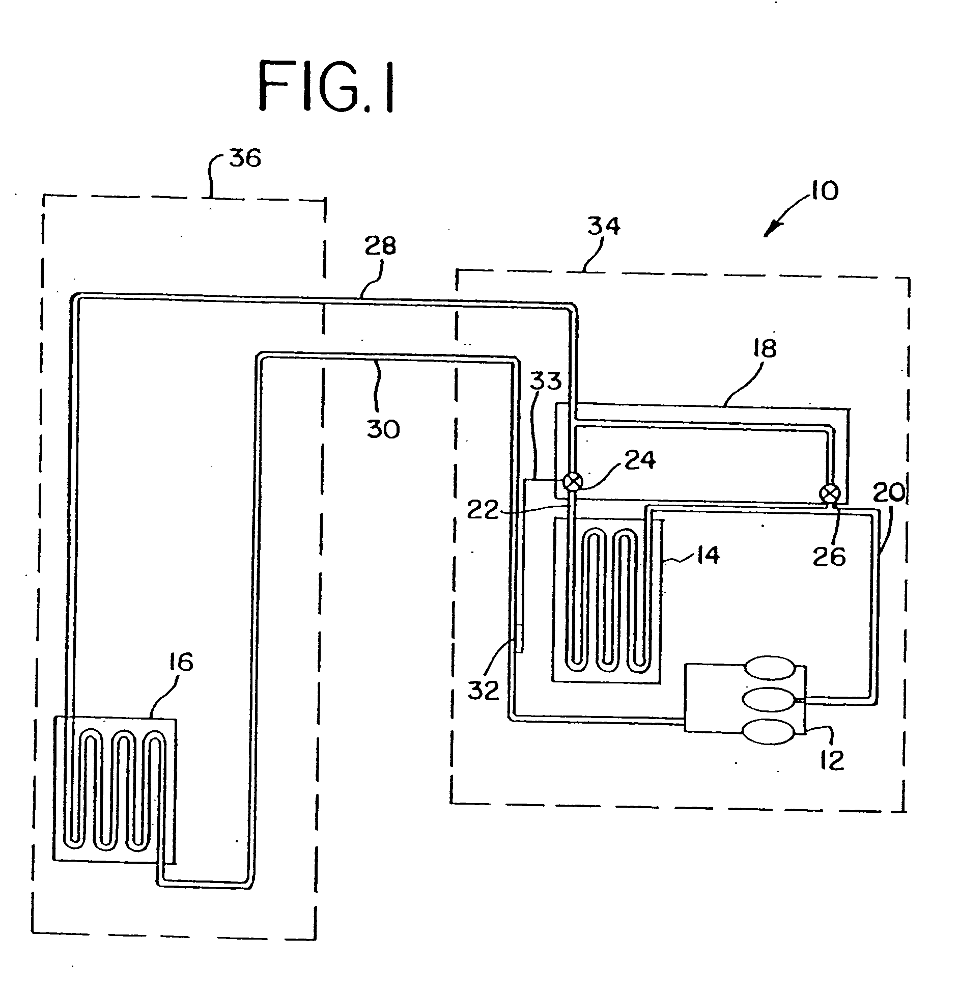
Figure 2 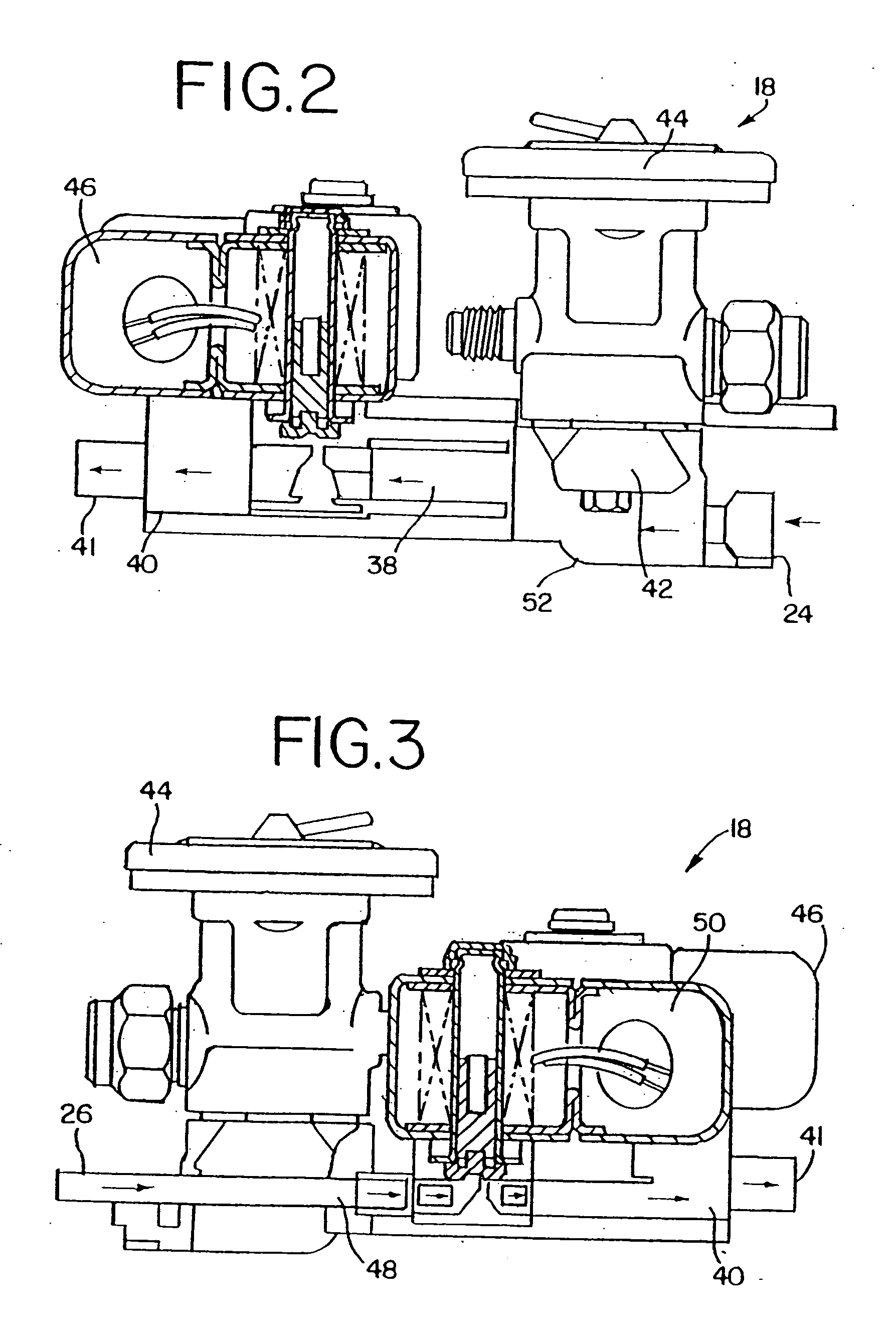
Figure 3
Abstract
Description
CROSS REFERENCE TO RELATED APPLICATIONS
[0001] This application is a continuation-in-part of U.S. patent application Ser. No. 10 / 129, 339, filed May 2, 2002, which is a National Stage of PCT / US00 / 14648, filed May 26, 2000. PCT / US00 / 14648 is a continuation-in-part of P.C.T. application PCT / US00 / 00663, filed Jan. 11, 2000, which was published in English and designated the United States and a continuation-in-part of U.S. patent application Ser. No. 09 / 431,830, filed Nov. 2, 1999, now U.S. Pat. No. 6,185,958. The contents of these prior applications are incorporated by reference.BACKGROUND
[0002] In a closed-loop vapor compression cycle, the heat transfer fluid changes state from a vapor to a liquid in the condenser, giving off heat, and changes state from a liquid to a vapor in the evaporator, absorbing heat during vaporization. A typical vapor-compression system includes a compressor for pumping a heat transfer fluid, such as a freon, to a condenser, where heat is given off as the vap...
Examples
example i
[0131] A 5-ft (1.52 m) Tyler Chest Freezer was equipped with a multifunctional valve in a refrigeration circuit, and a standard expansion valve was plumbed into a bypass line so that the refrigeration circuit could be operated as a conventional vapor compression system and as an XDX refrigeration system arranged in accordance with the invention. The refrigeration circuit described above was equipped with a saturated vapor line having an outside tube diameter of about 0.375 inches (0.953 cm) and an effective tube length of about 10 ft (3.048 m). The refrigeration circuit was powered by a Copeland hermetic compressor having a capacity of about ⅓ ton (338 kg) of refrigeration. A sensing bulb was attached to the suction line about 18 inches from the compressor. The circuit was charged with about 28 oz. (792 g) of R-12 refrigerant available from The DuPont Company. The refrigeration circuit was also equipped with a bypass line extending from the compressor discharge line to the saturated...
example ii
[0143] The Tyler Chest Freezer was configured as described above and further equipped with electric defrosting circuits. The low temperature operating test was carried out as described above and the time needed for the refrigeration unit to return to refrigeration operating temperature was measured. A separate test was then carried out using the electric defrosting circuit to defrost the evaporator. The time needed for the XDX system and an electric defrost system to complete defrost and to return to the 5° F. (−15° C.) operating set point appears in Table III below.
TABLE IIITIME NEEDED TO RETURN TO REFRIGERATION TEMPERATUREOF 5° F. (−15° C.) FOLLOWINGConventional SystemXDXwith Electric DefrostDefrost Duration (min)1036Recovery Time (min)24144
[0144] As shown above, the XDX system using forward-flow defrost through the multifunctional valve needs less time to completely defrost the evaporator, and substantially less time to return to refrigeration temperature.
example iii
[0145] A three door reach in freezer was set up in two configurations and tested to determine the ability of the freezer to meet defined acceptance criteria under each configuration. The tests were conducted using a Three-door Reach-In freezer powered by a Copeland compressor (part number KAKD-011E-CAV) and loaded with 24 ozs of R-404A refrigerant. The compression circuit used a FSE-1 / 2-ZP35 expansion valve. In the unmodified configuration, the system capacity was rated by the manufacturer at 4,280 BTU / hr and the evaporator capacity at 3,500 BTU / hr.
[0146] In the first (unmodified) configuration, the freezer was operated as a conventional vapor compression system, i.e. without the conversion of the heat transfer fluid to a high quality liquid vapor mixture before delivery to the evaporator. In this configuration, the evaporator coil consisted of a total of forty-two (42) passes of ⅜″ copper tubing. The evaporator coil was fed by a double feed through a distributor.
[0147] In the sec...