
Control unit used in machine tools
Patent Information
- Authority / Receiving Office
- US · United States
- Current Assignee / Owner
- Publication Date
- 2005-07-05
- Estimated Expiration
- Not applicable · inactive patent
Smart Images
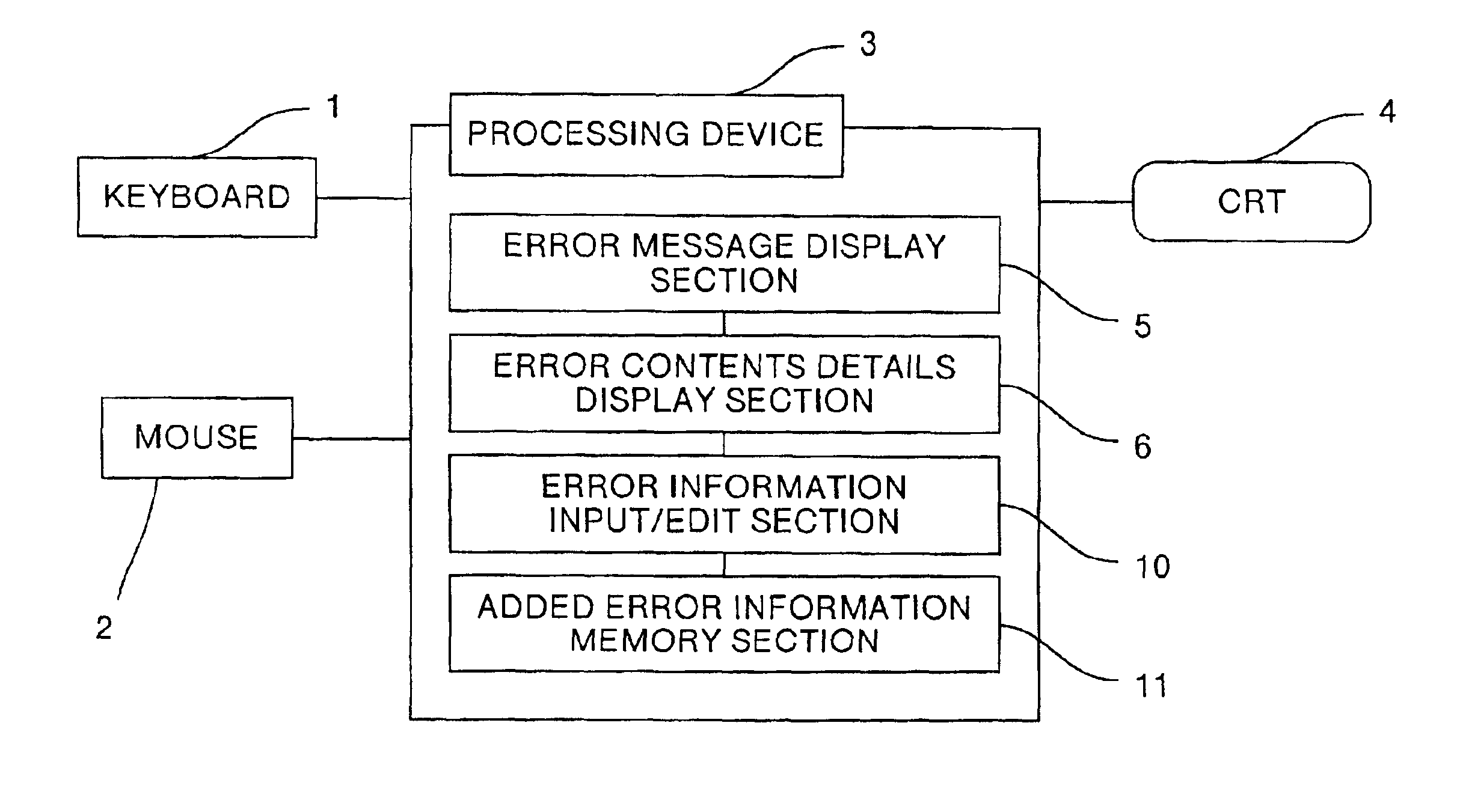
Figure 1 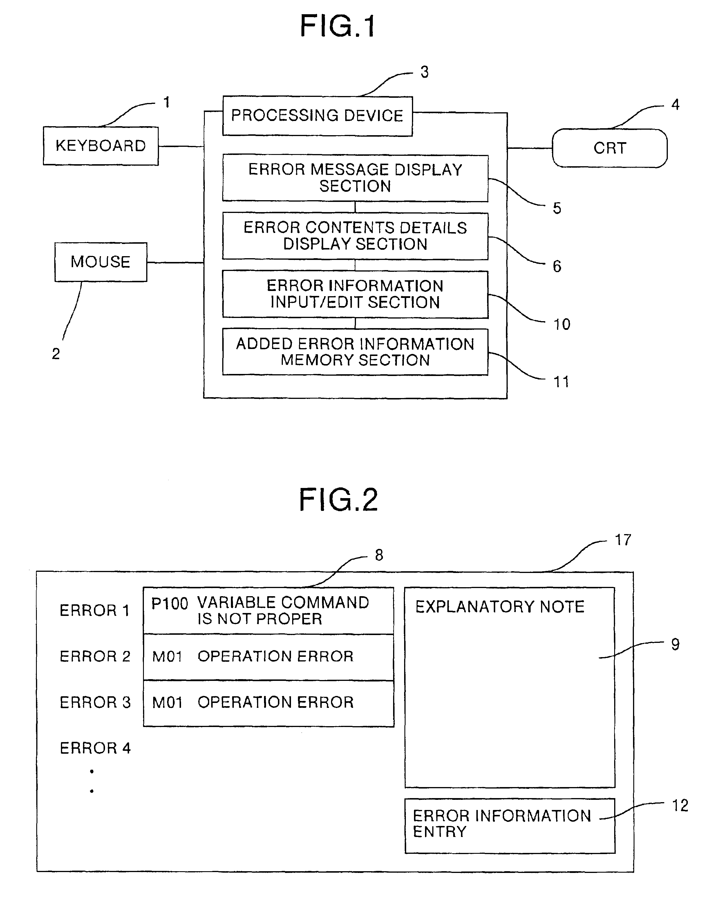
Figure 2 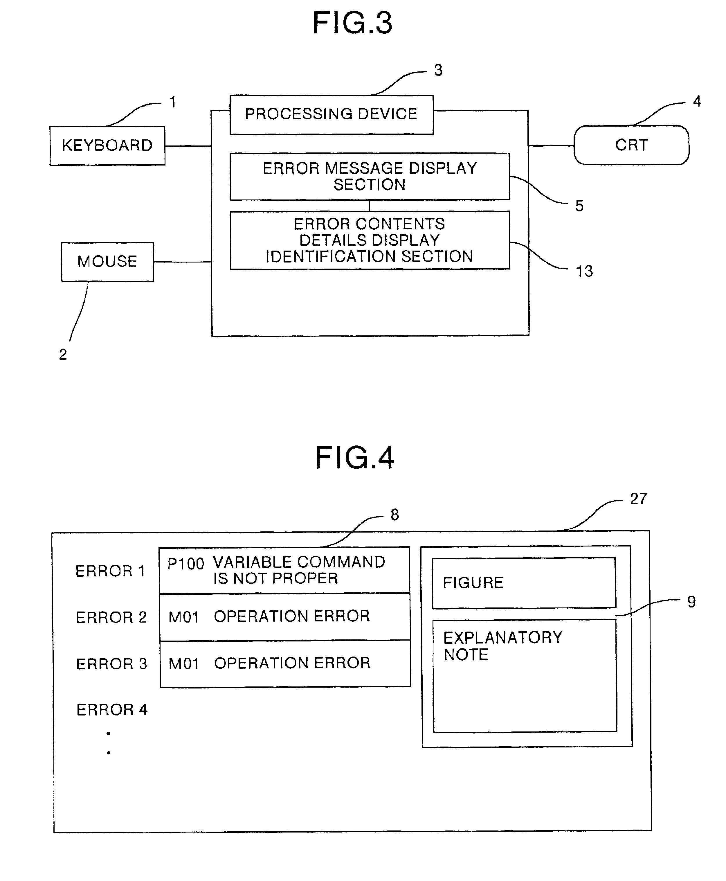
Figure 3
Abstract
Description
TECHNICAL FIELD
[0001] The present invention relates to a control unit, and more specifically, relates to a control unit used in machine tools.BACKGROUND ART
[0002] A schematic block diagram of a conventional control unit is shown in FIG. 7. As shown in FIG. 7, in this control unit, reference numeral 1 denotes a keyboard for inputting data, 2 denotes a mouse for choosing a button on the screen, 3 denotes a processing unit for controlling each processing, 4 denotes a CRT which displays data, 5 denotes an error message display unit and 6 denotes an error contents detailed display unit.
[0003] The conventional control unit operates as follows. The control unit displays the error display screen 7 shown in FIG. 8. If an error occurs in a machine to be controlled, for example, in a machine tool such as a laser beam machine, a primary error message corresponding to this error is displayed on an error number / name display section 8, and detailed contents of the error are displayed in an error cont...
Examples
first embodiment
[0025]A control unit according to the first embodiment of the present invention will now be described with reference to FIG. 1 and FIG. 2. FIG. 1 is a schematic block diagram of the control unit according to this embodiment, and FIG. 2 is a diagram showing an error display screen 17.
[0026]When an error occurs in a machine to be controlled (for example, a laser beam machine), an error number and an error name, being a primary error message corresponding to this error, are displayed in an error number / name display section 8 on the error display screen 17 by the error message display section 5. When a plurality of errors occurs at the same time, a plurality of errors are displayed in a plurality of lines at the same time. The error contents detailed display section 6 displays detailed contents of the error corresponding to the error number are displayed in the error contents display area 9. When a plurality of errors occurs at the same time, detailed contents of the error corresponding...
second embodiment
[0028]A control unit according to the second embodiment of the present invention will now be described with reference to FIG. 3 and FIG. 4. FIG. 3 is a schematic block diagram of the control unit according to this embodiment, and FIG. 4 is a diagram showing the error display screen 27.
[0029]When an error occurs, the error message display section 5 displays the error number and the error name corresponding to this error are in the error number / name display area 8 on the error display screen 27. When a plurality of errors occurs at the same time, a plurality of errors are displayed in a plurality of lines at the same time. The error contents detailed display identification section 13 judges whether or not there is a figure or an explanatory note corresponding to the error number. When it is judged, that there are both the figure and the explanatory note, these are displayed in an error contents display section 9. On the contrary, when it is judged, that there is only the explanatory n...
third embodiment
[0030]A control unit according to the third embodiment of the present invention will now be described with reference to FIG. 5 and FIG. 6. FIG. 5 is a schematic block diagram of the control unit according to this embodiment, and FIG. 6 is a diagram showing the error display screen 37.
[0031]When an error occurs, the error message display section 5 displays the error number and the error name corresponding to this error in the error number / name display area 8 on the error display screen 37. When a plurality of errors occurs at the same time, a plurality of errors are displayed in a plurality of lines at the same time. The error contents detailed display section 6 displays detailed contents of the error corresponding to the error number in the error contents display area 9. When a plurality of errors occurs at the same time, detailed contents of the error corresponding to the error number displayed at the head are displayed. In this case, a selection key corresponding to the error to b...