
System and method for sheet transporting using dual capstan rollers
a technology of plate-type imaging and transporting media, which is applied in the field of transporting media in the imaging system of the plate-type printer, can solve problems such as inefficient use of media, and achieve the effects of reducing media tendency, minimizing or substantially eliminating imaging artifacts, and eliminating imaging artifacts
Patent Information
- Authority / Receiving Office
- US · United States
- Patent Type
- Patents(United States)
- Current Assignee / Owner
- Publication Date
- 2006-05-09
- Estimated Expiration
- Not applicable · inactive patent
Smart Images
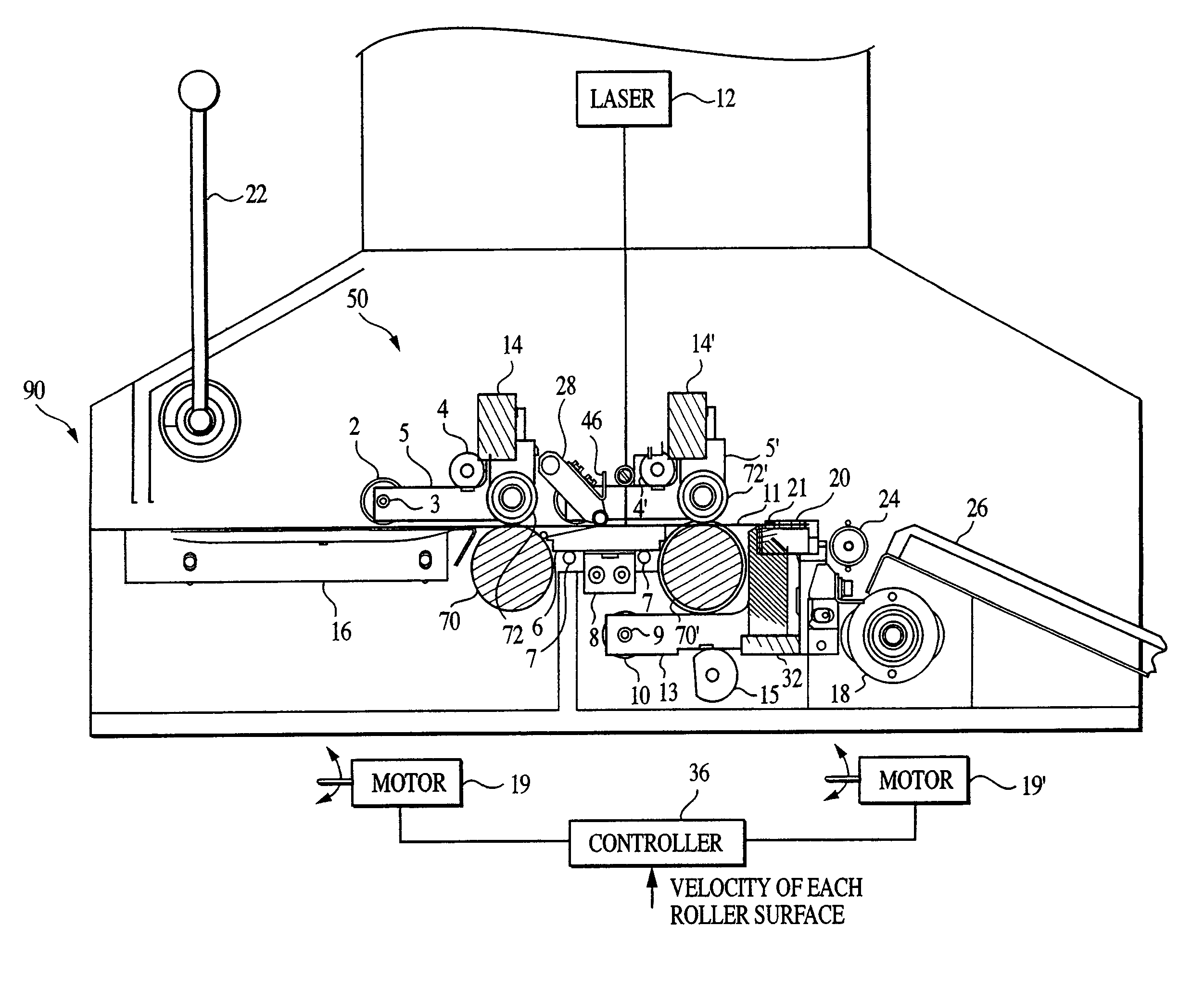
Figure 1 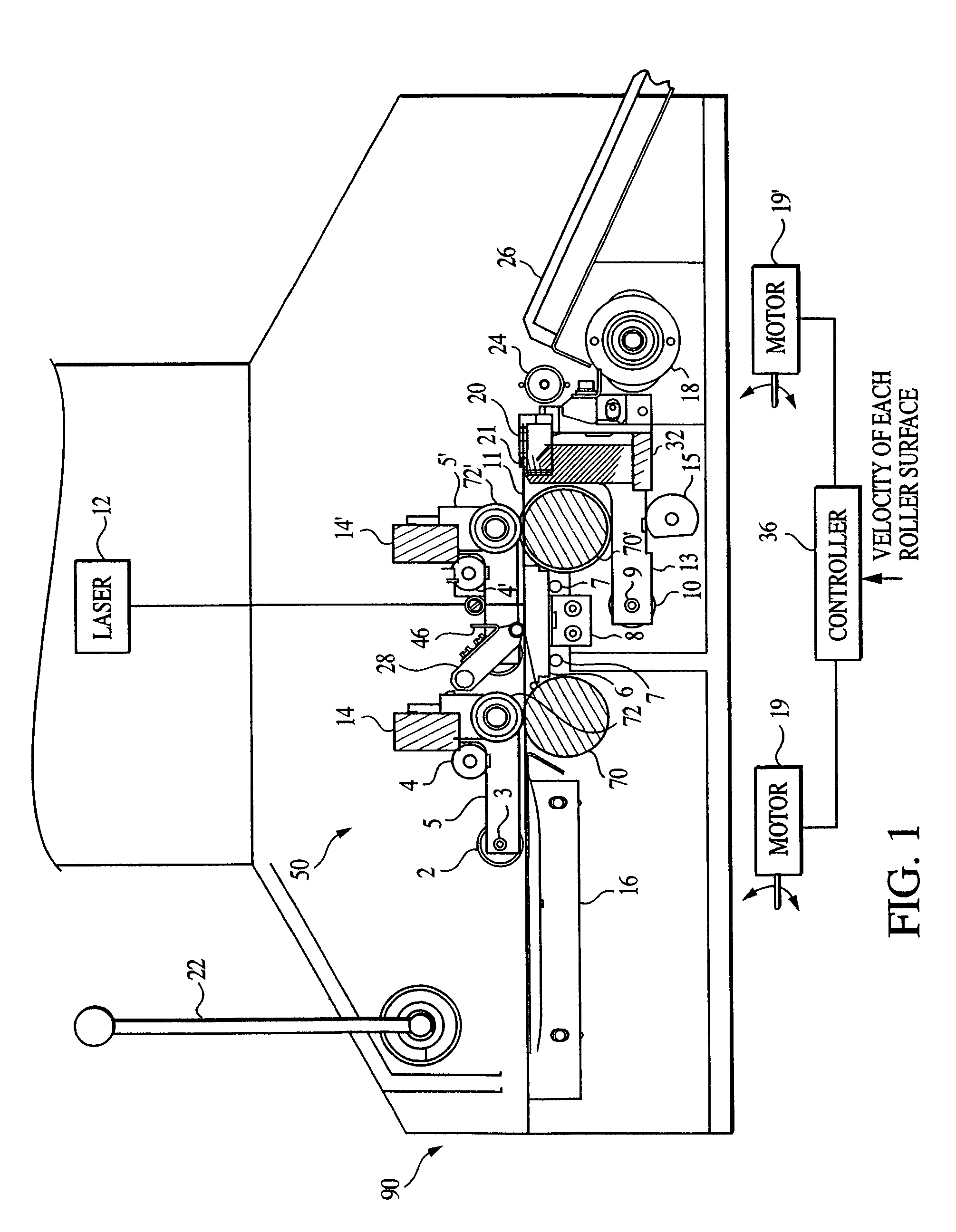
Figure 2 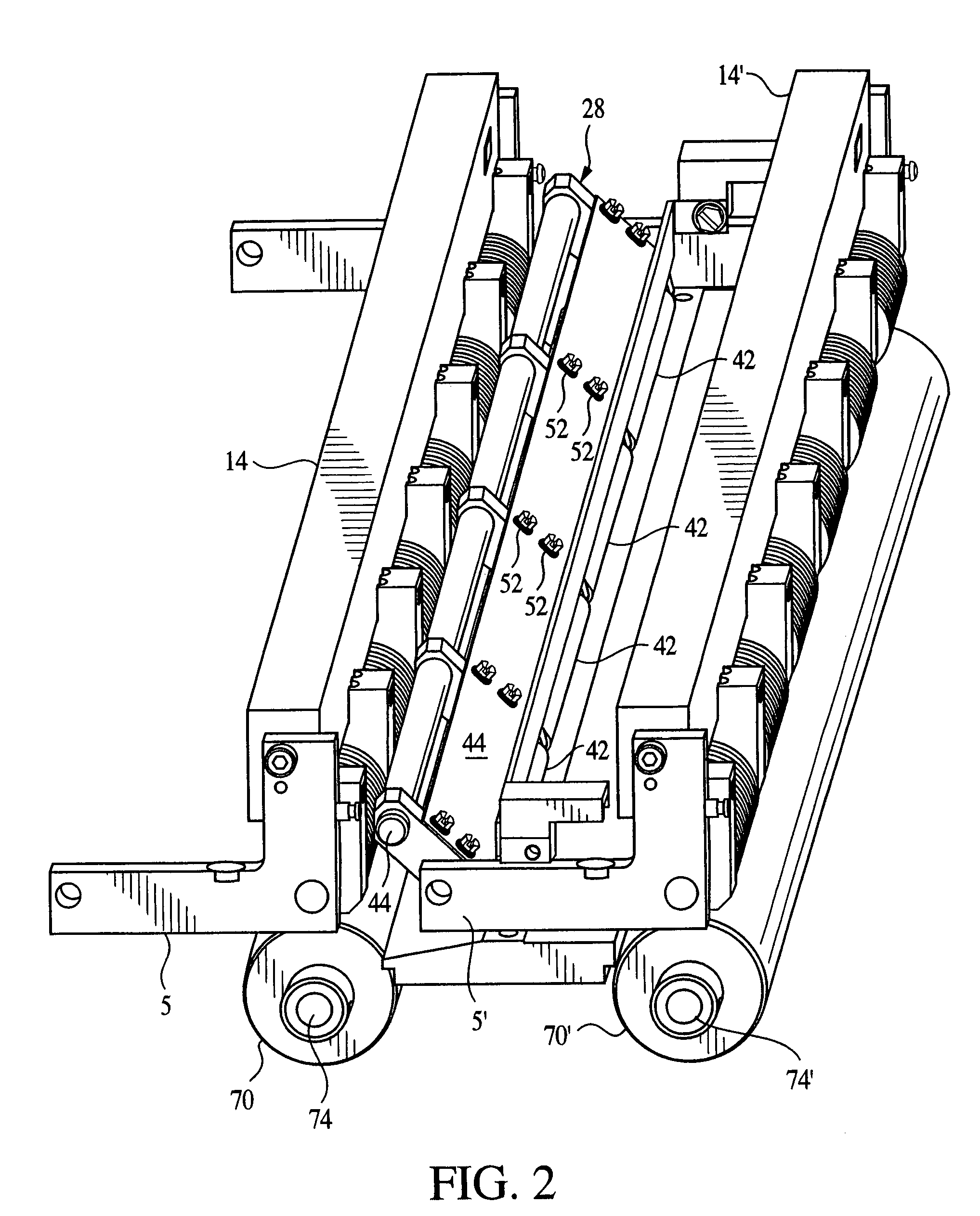
Figure 3
Abstract
Description
CROSS-REFERENCE TO RELATED APPLICATION
[0001] This application is a continuation of U.S. patent application Ser. No. 10 / 117,337, filed Apr. 8, 2002, which is hereby incorporated by reference herein in its entirety.BACKGROUND OF THE INVENTION
[0002] The present invention relates generally to transporting media and, more particularly, to transporting media in a platesetter imaging system.
[0003] In platesetting imaging systems in which media (e.g., metal and / or plastic sheet) are moved, conventional capstan drives cannot expose or form an image over an entire length of the media from end-to-end (i.e., from a leading edge of the media to a trailing edge of the media). This results in inefficient use of media, and use of a media size that is necessarily larger than an image formed thereon.
[0004] There remains a need for a platesetter media transport and imaging system that provides end-to-end use of media, as well as a substantially consistent image quality throughout the entire image.SUMMARY ...
Examples
Embodiment Construction
including the description of a preferred structure as embodying features of the invention will be best understood when read in reference to the accompanying figures wherein:
[0013]FIG. 1 is an elevation view of an exemplary platesetter imaging system embodying the present invention;
[0014]FIG. 2 is an exemplary perspective view of the upper and lower roller arrangement of the platesetter imaging system of FIG. 1;
[0015]FIG. 3A is an exemplary perspective view of the upper roller arrangement of the platesetter imaging system, showing additional details regarding roller arrangement;
[0016]FIG. 3B is an exemplary perspective view of the upper roller arrangement of the platesetter imaging system, showing the use of springs in keeping the rollers in contact with the medium;
[0017]FIG. 4 is an exemplary perspective view illustrating the alignment pins shown in FIG. 1;
[0018]FIG. 5 is an exemplary diagram showing the sequence of operation in transporting a recording medium during an imaging oper...