
Portable electronic spirometer
a spirometer and electronic technology, applied in the field of portable spirometers, can solve the problems of preventing a highly accurate or complete determination of flow properties, low level of accuracy of spirometers, and no electronic recording and transmission means of spirometers, etc., to achieve the effect of increasing the measured air pressur
Patent Information
- Authority / Receiving Office
- US · United States
- Patent Type
- Patents(United States)
- Current Assignee / Owner
- Publication Date
- 2006-06-20
- Estimated Expiration
- Not applicable · inactive patent
Smart Images
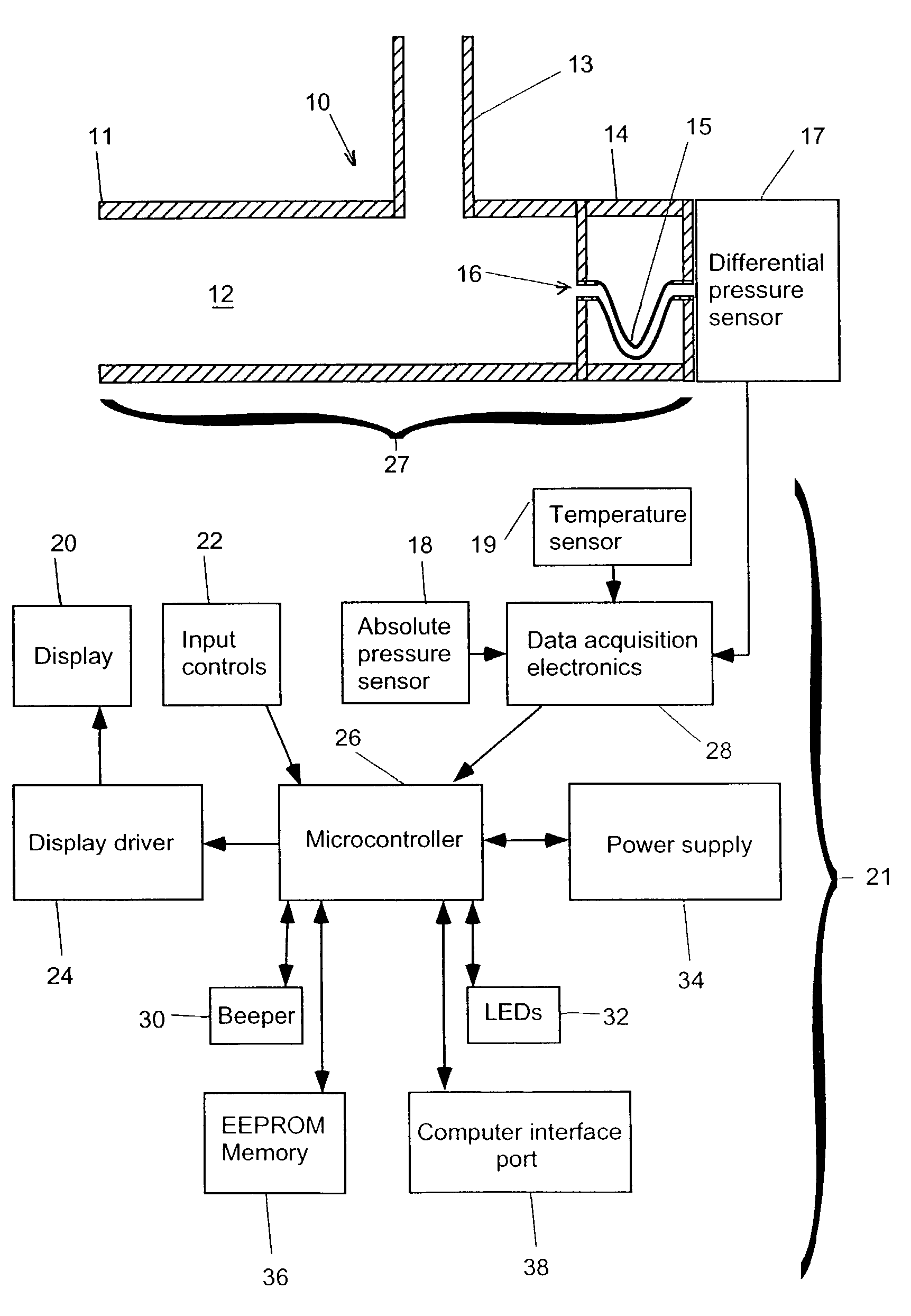
Figure 1 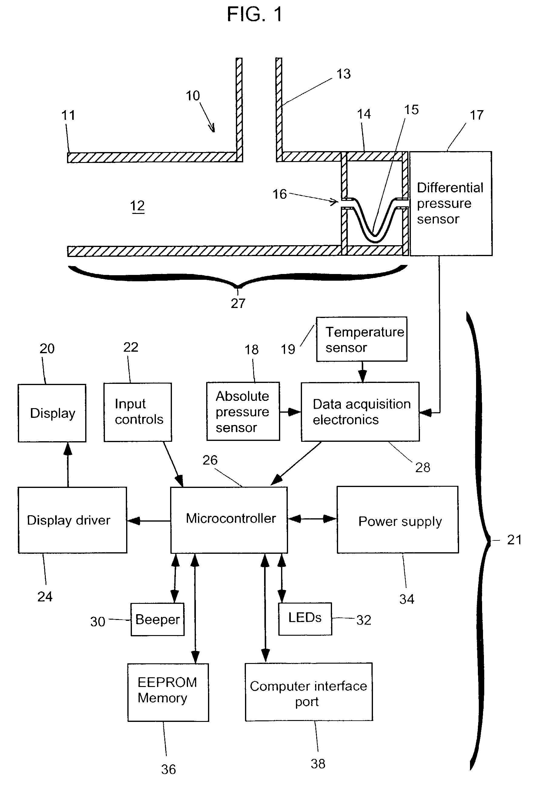
Figure 2 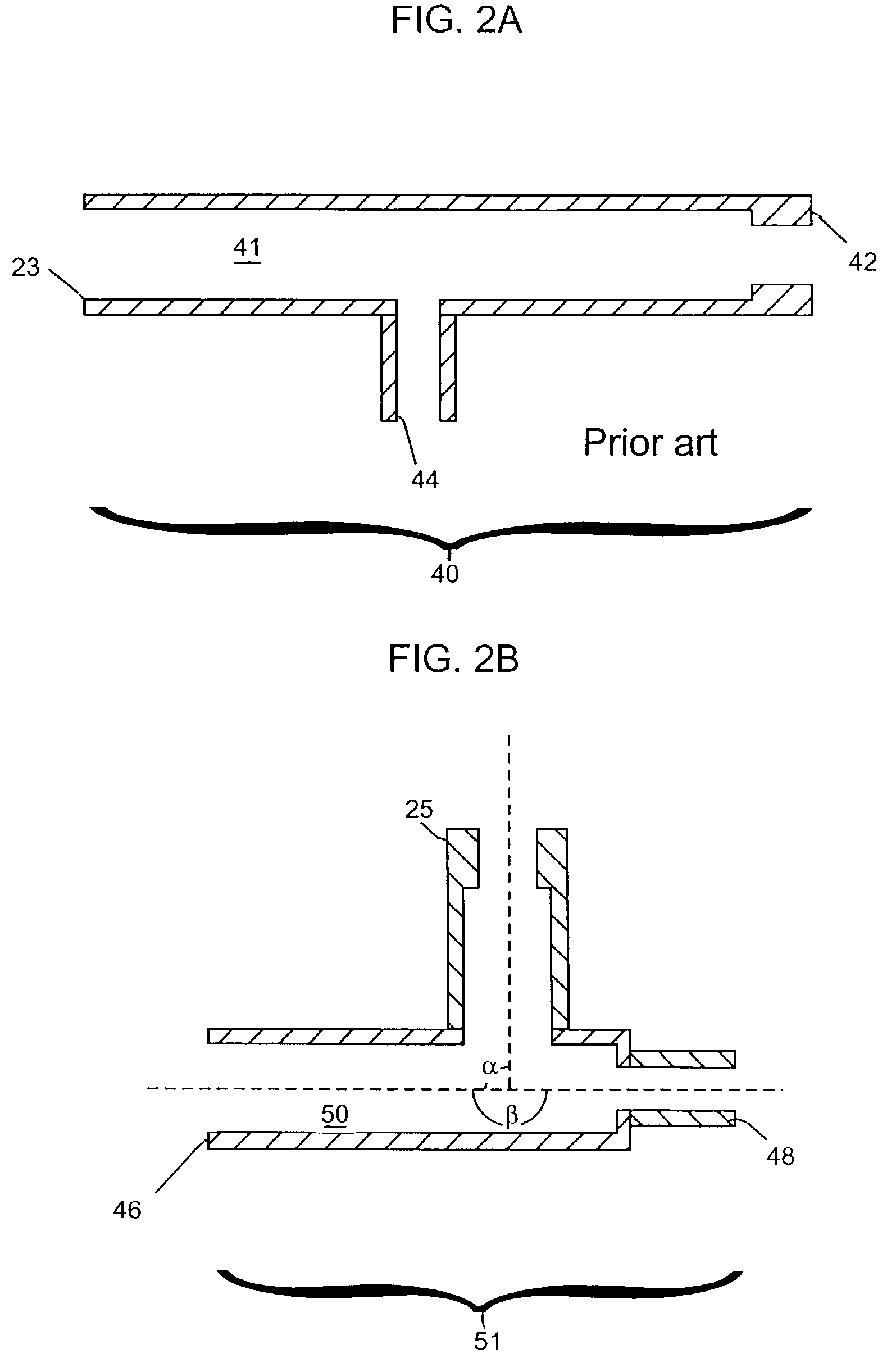
Figure 3
Abstract
Description
FIELD
[0001] The present invention relates to a portable spirometer for monitoring lung function and for transferring spirometer data to other computers.BACKGROUND OF THE INVENTION
[0002] A spirometer is a device that monitors respiration. A spirometer can be used for the diagnosis and monitoring of pulmonary diseases, particularly asthma and COPD (smoker's cough). Spirometers are also used to monitor the performance of athletes, as well as screen for occupational health problems such as black lung disease or silicosis. Spirometers are generally divided into two classes which have different specifications and purposes. The first class of spirometer are diagnostic spirometers which are used by physicians for the diagnosis of a person's respiratory condition. Diagnostic spirometers must be able to measure many different parameters of respiratory flow and must have a high degree of accuracy. The second class of spirometers are monitoring spirometers which are used to monitor the condition ...
Examples
Embodiment Construction
Spirometer Construction
[0030]Referring to FIG. 1, the spirometer 10 consists of a housing 27 having a flow chamber 12, with a mouthpiece 11 and a meander passageway structure 61. The meander passageway structure 61 consists of a housing compartment 14 having end walls 63 and 65 at opposite ends and a hollow meander tube 15 whose meander passageway 16 is bent and opens through end walls 63 and 65 to provide fluid communication between the flow chamber 12 and a differential pressure sensor 17. The meander tube 15 could be replaced by, for example, a block of material with a bore therethrough. A differential pressure sensor 17 is located at an end of the flow chamber 12 opposite the mouthpiece 11. The meander tube 15 is used to protect the pressure sensor 17 from the direct flow of air so that contaminants from a user's breath will not enter the pressure sensor 17. An outlet tube 13 intersects the flow chamber 12 transversely. The meander tube 15 and crosshatched area may be constructe...