
Ultrasonic flow meter including turbulators
a flow meter and ultrasonic technology, applied in the field can solve the problems of aerodynamically caused interference signals, inability to fit the surface of ultrasonic transducers, and inability to fit ultrasonic transducers, so as to facilitate the practical insertability and replacement of ultrasonic flow meter, and reduce aerodynamic interference signals
Patent Information
- Authority / Receiving Office
- US · United States
- Patent Type
- Patents(United States)
- Current Assignee / Owner
- Publication Date
- 2008-06-03
- Estimated Expiration
- Not applicable · inactive patent
Smart Images
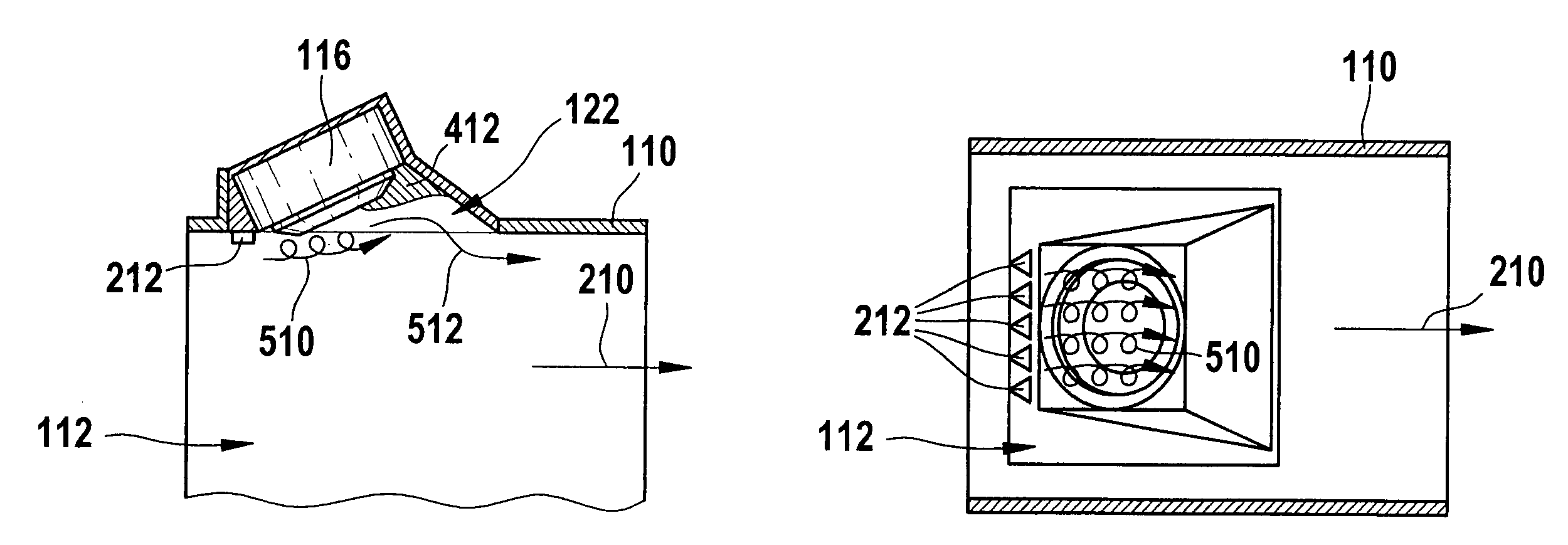
Figure 1 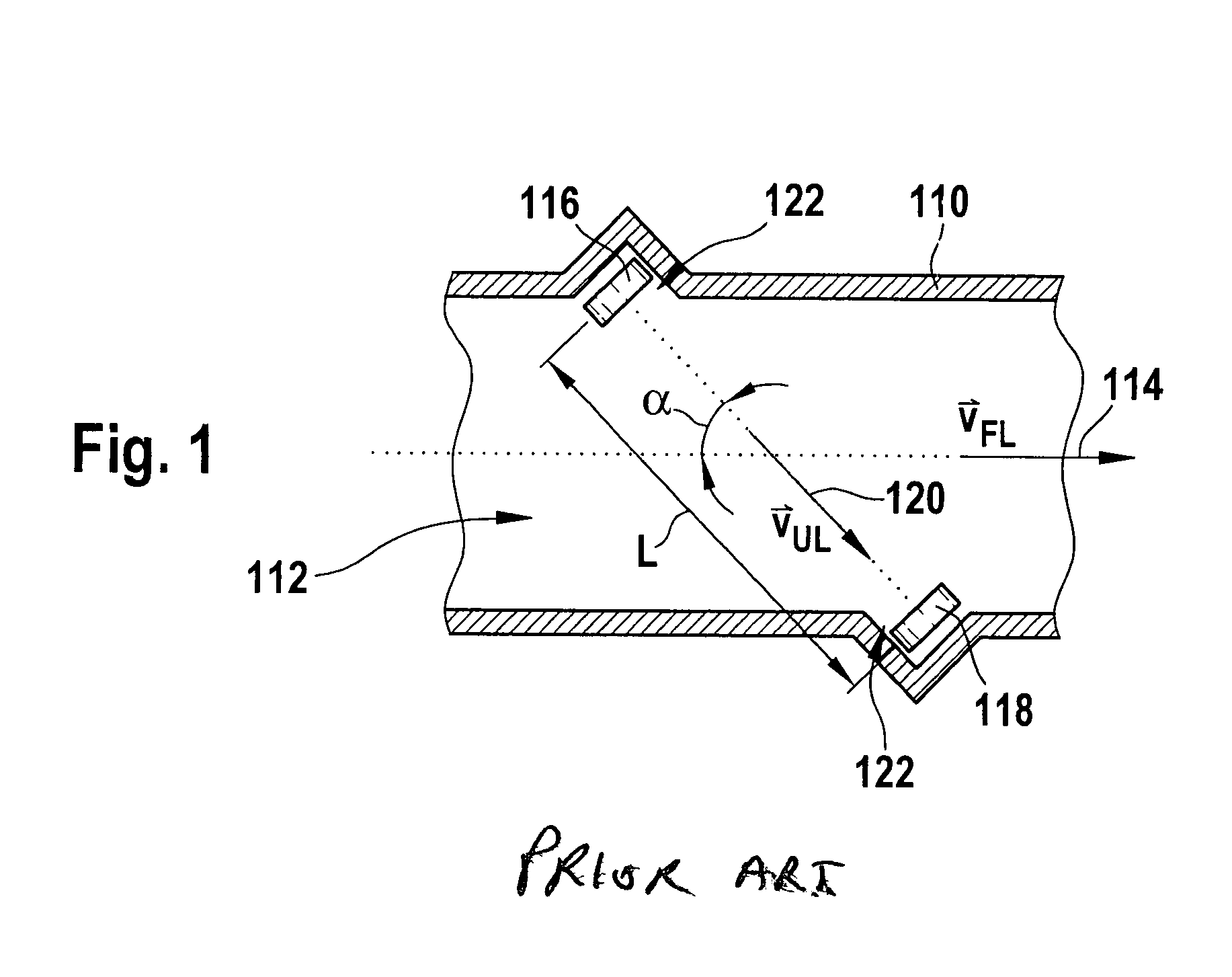
Figure 2 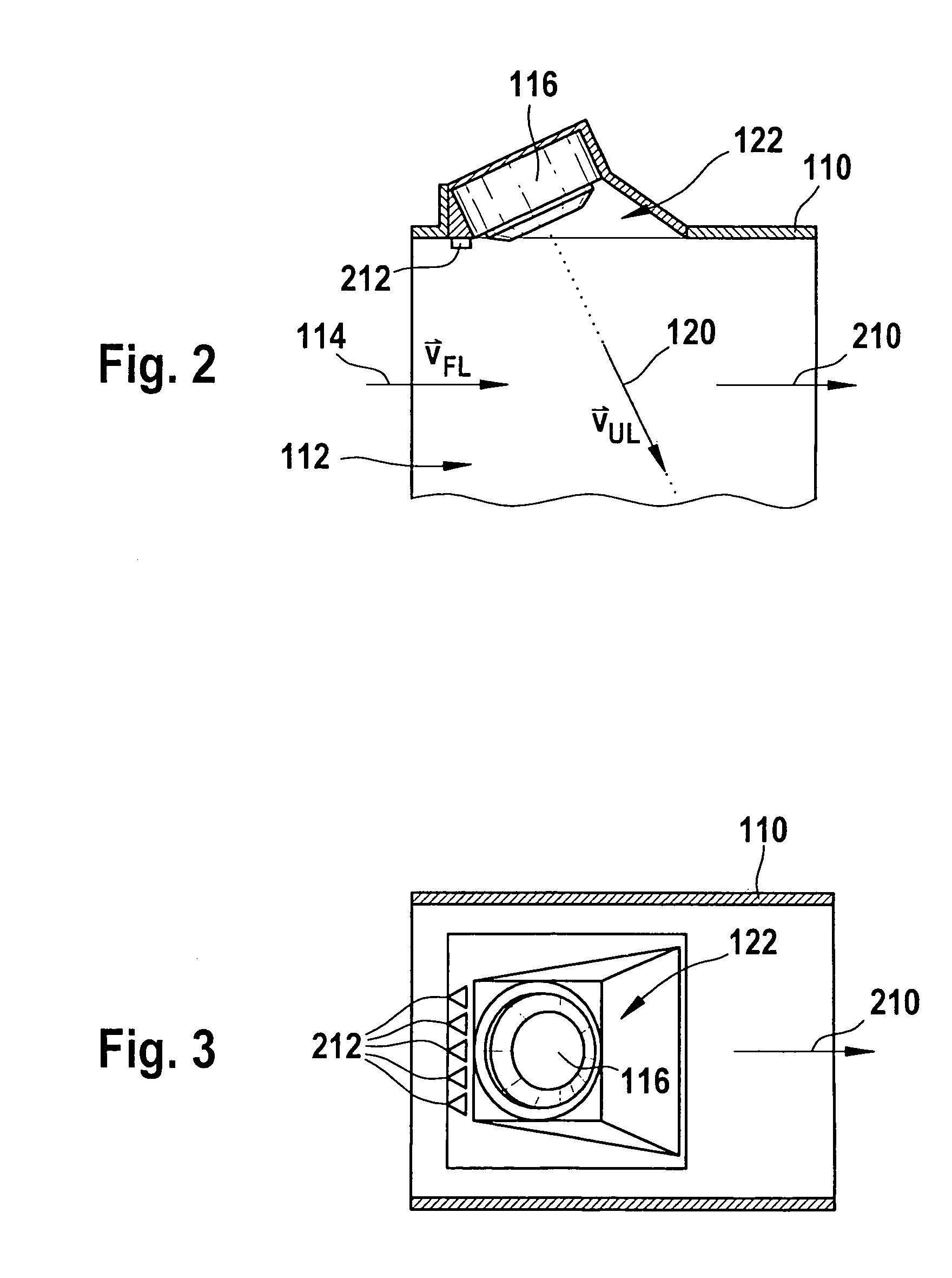
Figure 3
Abstract
Description
FIELD OF THE INVENTION
[0001] Ultrasonic flow meters are used in the automotive industry, in particular in the intake system of internal combustion engines, for measuring volume flow or mass flow.BACKGROUND INFORMATION
[0002] Typically ultrasonic transducers are used which are capable of both emitting ultrasonic waves into a fluid and receiving ultrasonic waves. The propagation time of ultrasonic signals which are transmitted from an emitter to a receiver is influenced by the flow of the fluid. It is possible to infer the flow velocity of the fluid from the degree of influence of the propagation time.
[0003] British Published Patent Application No. 2 101 318 describes an ultrasonic flow meter in which two ultrasonic transducers are mounted on opposite sides of a pipe through which a fluid flows. The transducers are situated slightly offset with respect to one another, so that ultrasonic waves emitted by one transducer and received by the second transducer propagate at an angle to the flow...
Examples
Embodiment Construction
[0027]The principle of ultrasonic flow measuring has been explained above with reference to FIG. 1. Linear systems (as in FIG. 1) or reflection systems may be used, for example. FIGS. 2 through 3 show a detail of an embodiment according to the present invention of an ultrasonic flow meter. The detail includes only an area around an ultrasound sensor 116, which is embedded into a wall of a flow pipe 110. A fluid 112 having a main flow direction 210, which is parallel to flow velocity 114, flows through flow pipe 110. As explained previously with reference to FIG. 1, a protrusion 122 is formed upstream from ultrasound sensor 116, within which burble zones of the flow of fluid 112 are formed.
[0028]As the cutaway view having the section plane parallel to main flow direction 210 in FIG. 2 and the view from below according to FIG. 3 show, in this embodiment of the present invention, turbulators 212 are situated upstream from protrusion 122 on the wall of flow pipe 110. In this case, turbu...