
Ultrasound system and method for measuring bladder wall thickness and mass
a technology of ultrasound imaging and measurement of bladder wall thickness, applied in the field of ultrasound imaging systems and methods, can solve the problems of unsatisfactory hypertrophy of bladder muscle, renal failure, patient death, etc., and achieve the effect of improving accuracy and precision of wall location loci
Patent Information
- Authority / Receiving Office
- US · United States
- Patent Type
- Patents(United States)
- Current Assignee / Owner
- Publication Date
- 2009-11-03
Smart Images
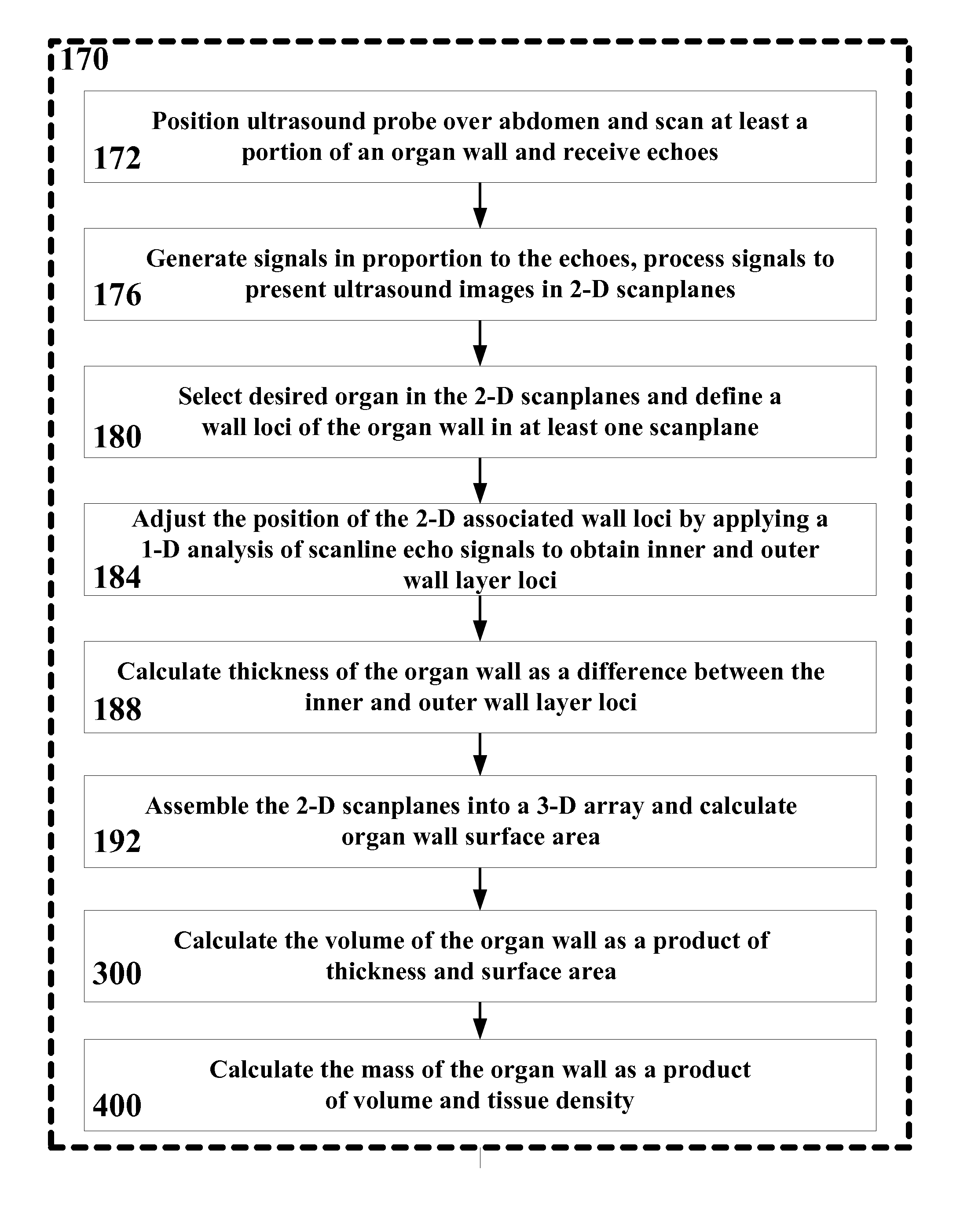
Figure 1 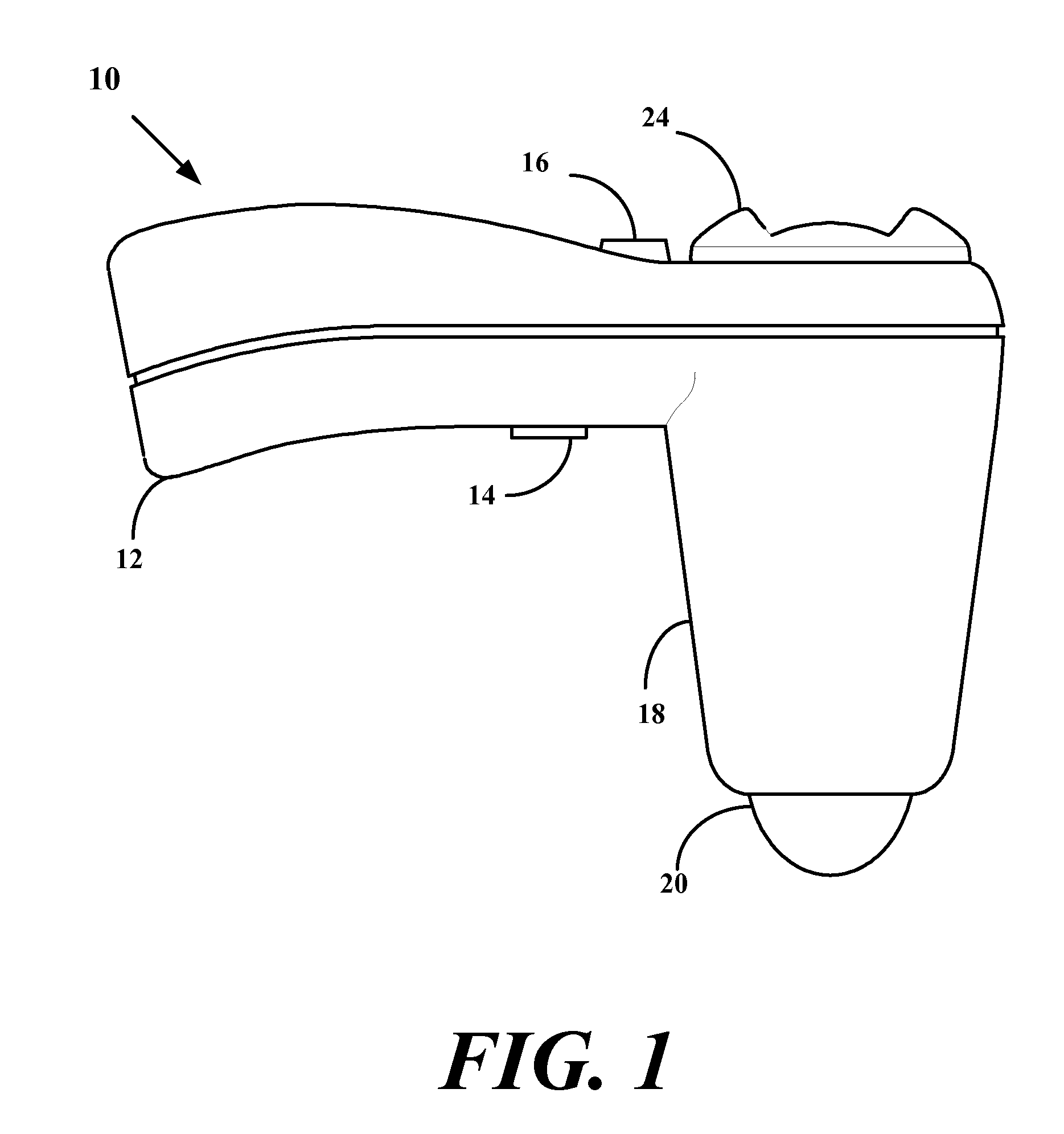
Figure 2 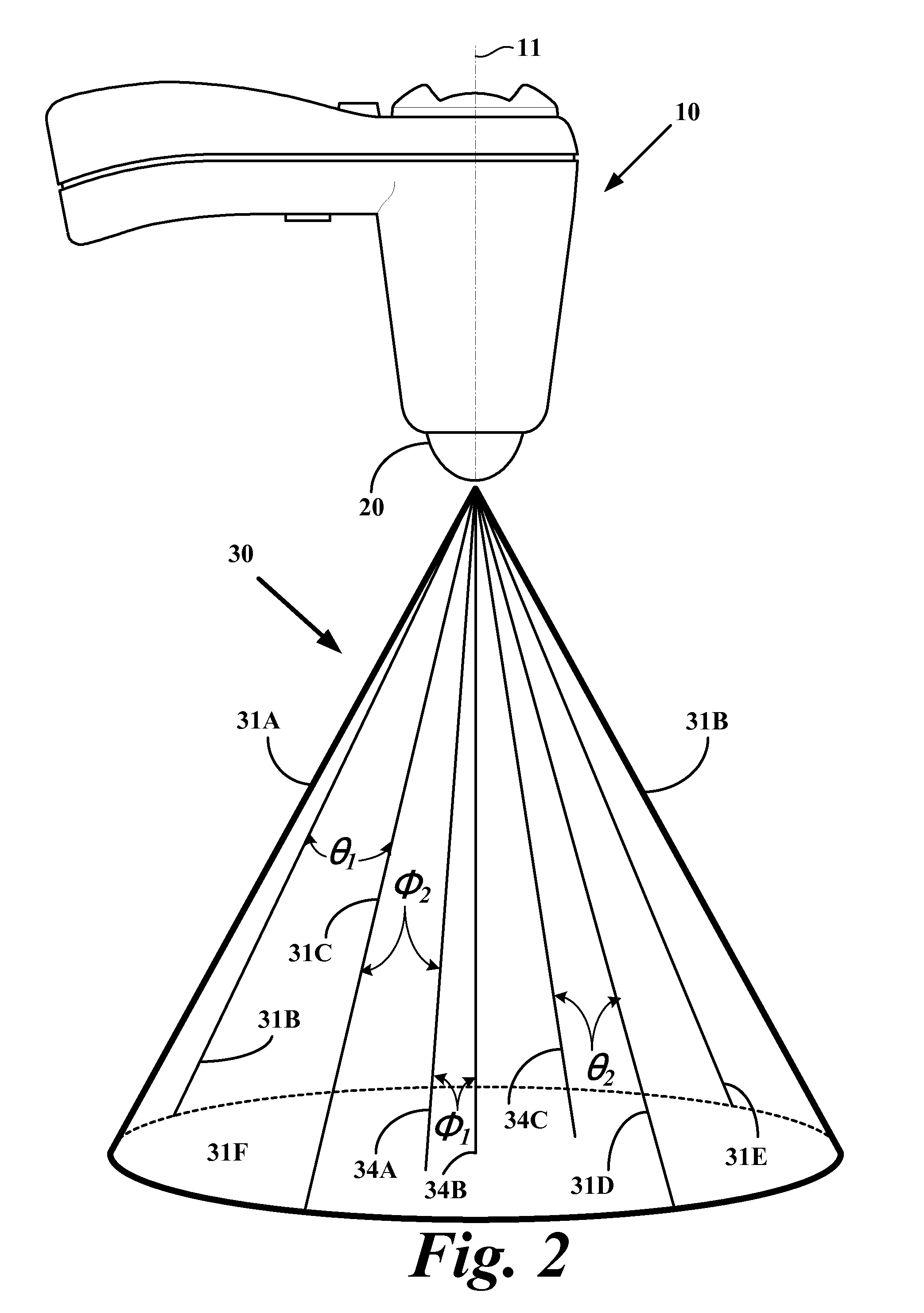
Figure 3
Abstract
Description
PRIORITY CLAIM
[0001] This application claims priority to U.S. Provisional Patent Application Ser. No. 60 / 566,823, filed Apr. 30, 2004; to U.S. Provisional Patent Application Ser. No. 60 / 566,818, filed Apr. 30, 2004; and to U.S. Provisional Patent Application Ser. No. 60 / 545,576, filed Feb. 17, 2004. This application also claims priority to and is a continuation-in-part of U.S. patent application Ser. No. 11 / 064,114 filed Feb. 17, 2005.
[0002] This application is also a continuation-in-part of and claims priority to U.S. application Ser. No. 11 / 010,539 filed Dec. 13, 2004, which claims priority to PCT / EP03 / 07807 filed Jul. 17, 2003, which is also a continuation of and claims priority to UK Application Serial No. 0218547.8 filed Aug. 9, 2002; and a continuation-in-part of and claims priority to U.S. patent application Ser. No. 10 / 704,996, filed Feb. 3, 2005, which is a continuation-in-part of and claims priority to PCT / EP03 / 07807 filed Jul. 17, 2003, which also is a continuation-in-part ...
Examples
Embodiment Construction
[0102]FIG. 1 is a side elevational view of an ultrasound transceiver 10. Transceiver 10 includes a transceiver housing 18 having an outwardly extending handle 12 suitably configured to allow a user to manipulate transceiver 10. The handle 12 includes a trigger 14 that allows the user to initiate an ultrasound scan of a selected anatomical portion, and a cavity selector 16, described below. Transceiver 10 includes a transceiver dome 20 that contacts a surface portion of the patient when the selected anatomical portion is scanned to provide an appropriate acoustical impedance match and to properly focus ultrasound energy as it is projected into the anatomical portion. The transceiver 10 further includes an array of separately excitable ultrasound transducer elements (not shown in FIG. 1) positioned within the housing 18. The transducer elements are suitably positioned within the housing 18 to project ultrasound energy outwardly from the dome 20, and to permit reception of acoustic ref...