
Wire harness
a wire harness and wire technology, applied in the direction of electrical/fluid circuits, electrical apparatus, vehicle components, etc., can solve the problems of promoting damage and possibly damaging and achieve the effect of suppressing damage to the electrically conductive path
Patent Information
- Authority / Receiving Office
- US · United States
- Patent Type
- Patents(United States)
- Current Assignee / Owner
- Publication Date
- 2017-10-03
Smart Images
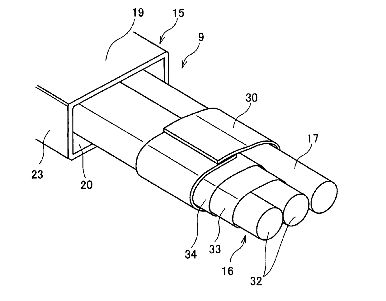
Figure 1 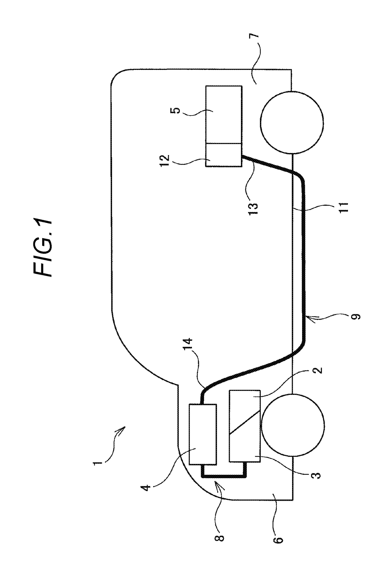
Figure 2 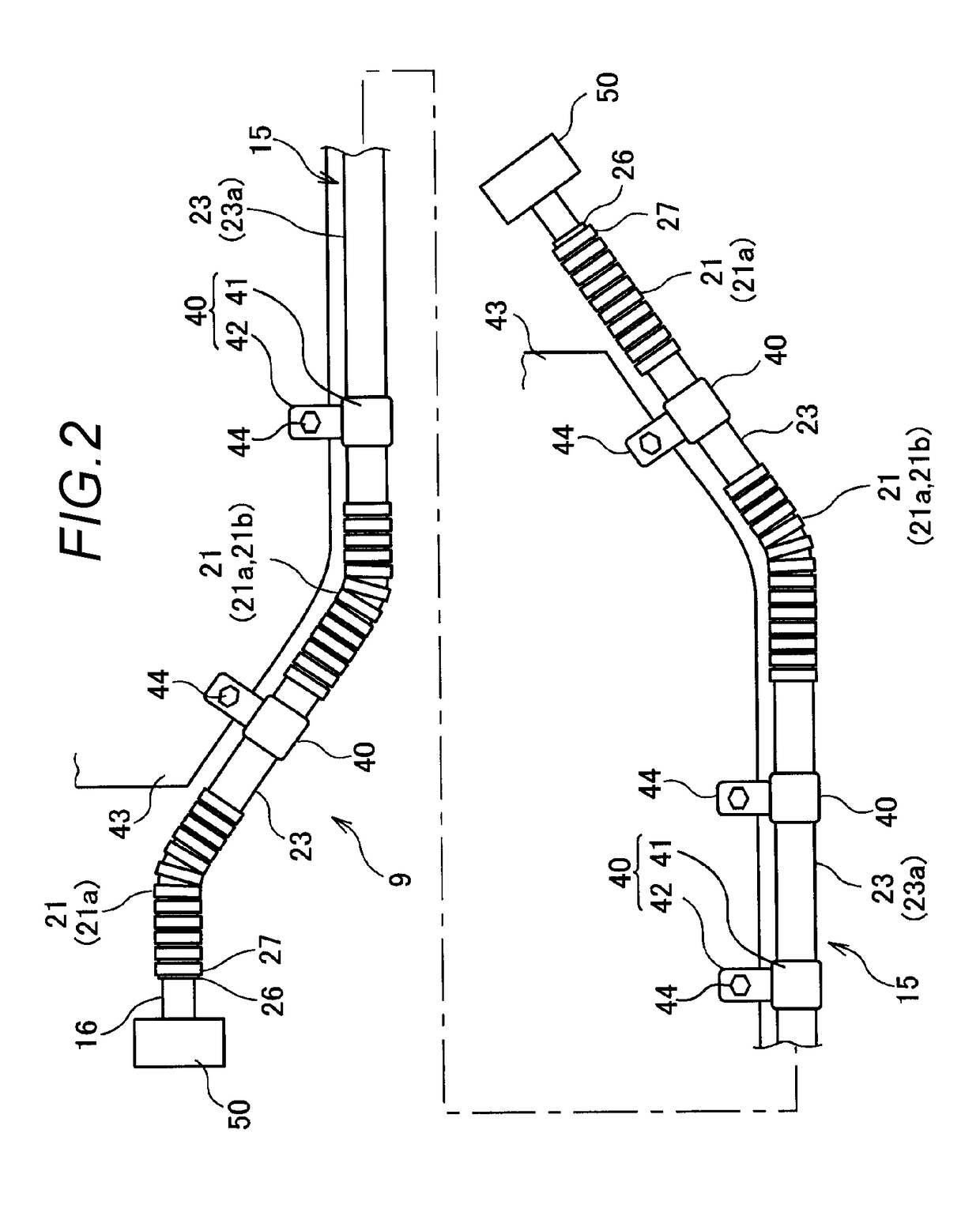
Figure 3
Abstract
Description
CROSS REFERENCE TO RELATED APPLICATIONS
[0001] This application is a continuation of PCT application No. PCT / JP2014 / 068364, which was filed on Jul. 9, 2014 based on Japanese Patent Application (No. 2013-146318) filed on Jul. 12, 2013, the contents of which are incorporated herein by reference.BACKGROUND OF THE INVENTION
[0002] Field of the Invention
[0003] The present invention relates to a wire harness.
[0004] Description of Related Art
[0005] Usually, a wire harness is known which electrically connects together high voltage devices mounted on a hybrid motor vehicle or an electric vehicle. The wire harness is formed with an electrically conductive path and a sheath member which accommodates the electrically conductive path therein as main members. The sheath member is formed with a hollow tubular member, which is desired to be hardly bent even when a bending stress is applied thereto by considering a protection of the electrically conductive path, a regulation of the path and a working prope...
Examples
Embodiment Construction
[0020]FIG. 1 is a schematic view showing an arranged state of a wire harness 9 according to the present embodiment. The wire harness 9 according to the present embodiment is used for a hybrid motor vehicle 1 and arranged in a prescribed position of the hybrid motor vehicle 1.
[0021]The hybrid motor vehicle 1 is a vehicle which is driven by combining together two powers of an engine 2 and a motor unit 3. To the motor unit 3, an electric power from a battery (a battery pack) is supplied through an inverter unit 4. The engine 2, the motor unit 3 and the inverter unit 4 are mounted on an engine room 6 in the vicinity of front wheels. Further, the battery 5 is mounted on a rear part 7 of the motor vehicle in the vicinity of rear wheels, however, the battery may be mounted in an interior of the motor vehicle located in a rear part of the engine room 6.
[0022]The motor unit 3 and the inverter unit 4 are connected together by a wire harness 8 for a high voltage. Further, the battery 5 and the...