

Pump type hydraulic coupler
A coupling and hydraulic technology, which is applied in the direction of clutches, clutches, fluid clutches, etc., can solve the problems of loss of engine braking function, clutch cannot be smoothly clutched, and no climbing function, etc., to achieve low manufacturing cost, space saving, and stable work good sex effect
- Summary
- Abstract
- Description
- Claims
- Application Information
AI Technical Summary
Problems solved by technology
Method used
Image

Examples
Embodiment 1
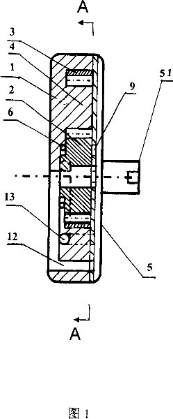
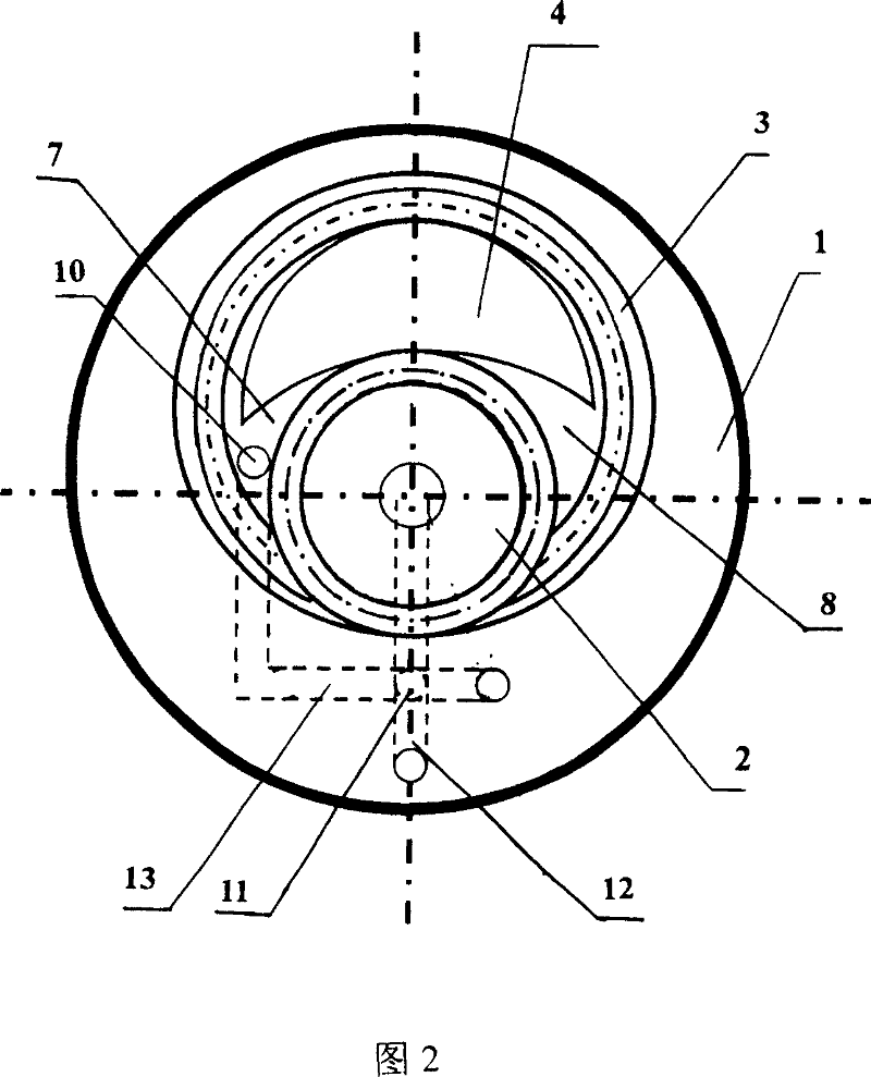
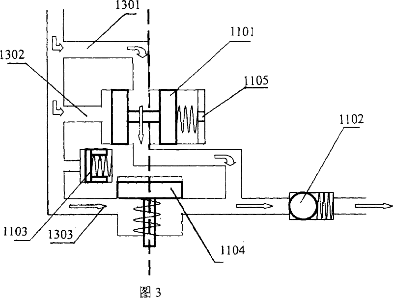
[0019] Referring to Fig. 1, Fig. 2 and Fig. 3, the inside of the housing 1 is coaxially connected with the pinion 2, which meshes with the large ring gear 3, and there is a crescent partition 4 between the pinion gear and the large ring gear. The casing back cover 5 is fixedly connected with the casing, the shaft center of the casing back cover is fixedly connected with the pump shaft 51, and the one-way clutch 6 is fixedly connected at one end of the connection between the pinion and the casing. The partition plate, the housing and the housing back cover respectively form a high-pressure oil chamber 7 and a low-pressure oil chamber 8. There are low-pressure oil passages 12 in the pump shaft, the housing back cover, the pinion, and the housing. There is an oil inlet hole 9, and there is a high-pressure oil hole 10 in the high-pressure oil chamber. The high-pressure oil hole is connected to the high-pressure oil circuit 13. 1101 is connected to the oil inlet, the pressure valve...
Embodiment 2
[0021] Referring to Fig. 1, Fig. 2 and Fig. 4, the inside of the housing 1 is coaxially connected with the pinion 2, which meshes with the large ring gear 3, and there is a crescent partition 4 between the pinion gear and the large ring gear. The casing back cover 5 is fixedly connected with the casing, the shaft center of the casing back cover is fixedly connected with the pump shaft 51, and the one-way clutch 6 is fixedly connected at one end of the connection between the pinion and the casing. The partition plate, the housing and the housing back cover respectively form a high-pressure oil chamber 7 and a low-pressure oil chamber 8. There are low-pressure oil passages 12 in the pump shaft, the housing back cover, the pinion, and the housing. There is an oil inlet hole 9, and there is a high-pressure oil hole 10 in the high-pressure oil chamber. The high-pressure oil hole is connected to the high-pressure oil circuit 13. The oil inlet connection of 1101, branch four 1304 and...
Embodiment 3
[0024]Referring to Fig. 1, Fig. 2 and Fig. 5, the inside of the housing 1 is coaxially connected with the pinion 2, which meshes with the large ring gear 3, and there is a crescent partition 4 between the pinion gear and the large ring gear. The casing back cover 5 is fixedly connected with the casing, the shaft center of the casing back cover is fixedly connected with the pump shaft 51, and the one-way clutch 6 is fixedly connected at one end of the connection between the pinion and the casing. The partition plate, the housing and the housing back cover respectively form a high-pressure oil chamber 7 and a low-pressure oil chamber 8. There are low-pressure oil passages 12 in the pump shaft, the housing back cover, the pinion, and the housing. There is an oil inlet hole 9, and there is a high-pressure oil hole 10 in the high-pressure oil chamber. The high-pressure oil hole is connected to the high-pressure oil circuit 13. The oil inlet connection of 1101, branch four 1304 and ...
PUM
 Abstract
Description
Claims
Application Information