Synchronous operation set

A technology of synchronous operation and synchronous frequency, used in nonlinear optics, instruments, optics, etc., can solve the problems of design instability, difference frequency, voltage ripple, etc., to improve the ripple phenomenon, the circuit structure is simple, and the stability is increased. Effect

A technology of synchronous operation and synchronous frequency, used in nonlinear optics, instruments, optics, etc., can solve the problems of design instability, difference frequency, voltage ripple, etc., to improve the ripple phenomenon, the circuit structure is simple, and the stability is increased. Effect

CN100397198CInactive Publication Date: 2008-06-25BEYOND INNOVATION TECH

Image

  • Synchronous operation set
  • Synchronous operation set
  • Synchronous operation set

Examples


Embodiment Construction

[0066] In order to further explain the technical means and effects of the present invention to achieve the intended purpose of the invention, the following in conjunction with the accompanying drawings and preferred embodiments, the specific implementation, structure, features and effects of the synchronous operation device proposed according to the present invention, Details are as follows.

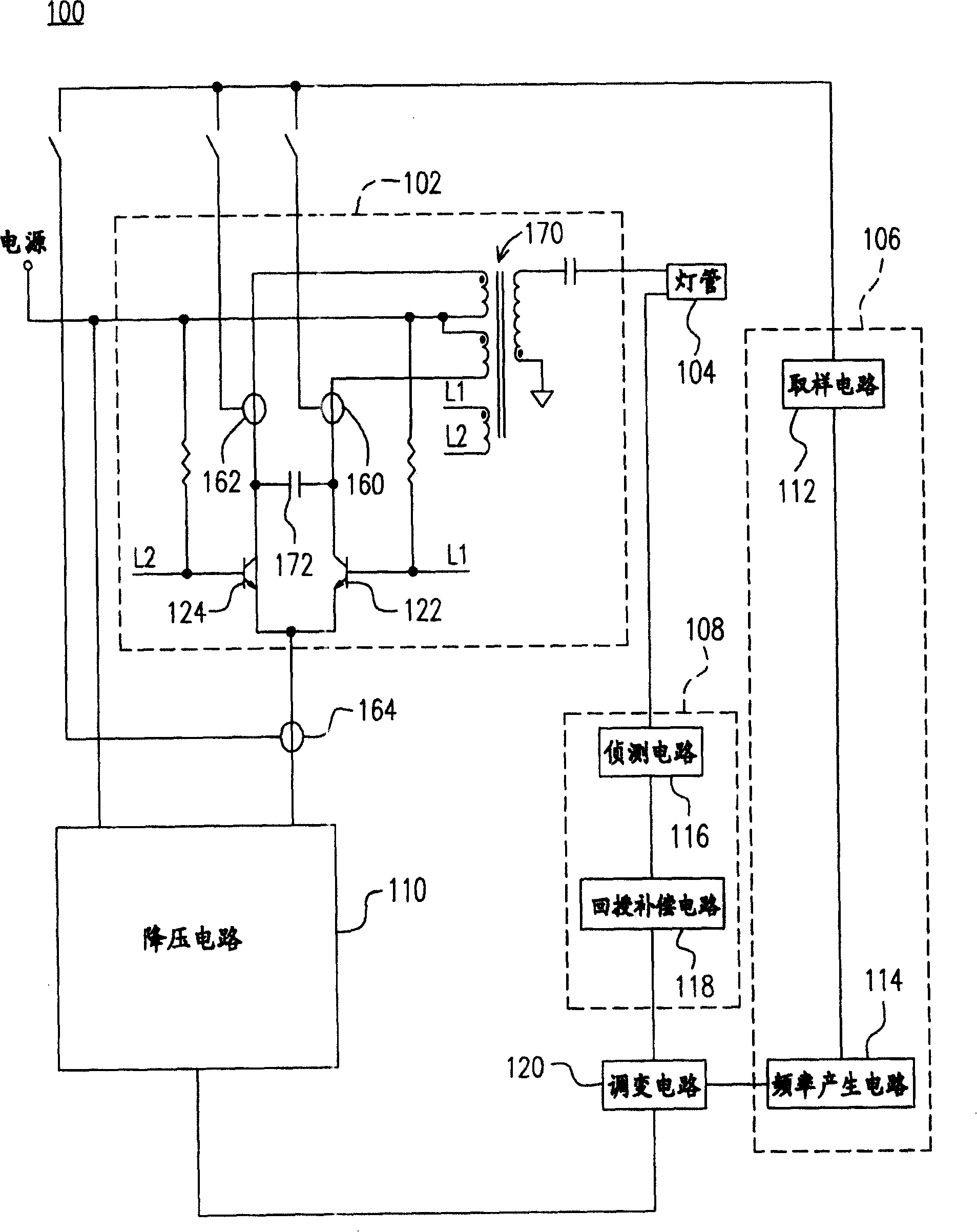
[0067] see figure 1 Shown is a circuit block diagram of a synchronous operation device according to a preferred embodiment of the present invention. The synchronous operation device 100 includes: a lamp tube 104 , a self-oscillating conversion circuit 102 , a sampling and frequency generating circuit 106 , a detection and feedback circuit 108 , a modulating circuit 120 and a step-down circuit 110 . Wherein, as those skilled in the art can easily know, the self-oscillating conversion circuit 102 can be, for example, a DC / AC converter to provide the lamp tube 104 with AC power. In addit...


PUM


Abstract

A synchronous operation device consists of light tube, natural vibration converting circuit, sampling and frequency generating circuit, detection and feedback circuit, adjusting circuit and voltage dropping circuit. It is featured as sampling natural vibration frequency by preset sampling point in natural vibration converting circuit or by preset sampling point of said converting circuit and voltage dropping circuit to make control signal outputted from adjusting circuit synchronize to natural vibration frequency for improving ripple phenomenon of high voltage output.

Description

technical field [0001] The present invention relates to a synchronous operation device, in particular to a synchronous operation device for synchronizing self-oscillation with frequency of converter and step-down circuit. Background technique [0002] The use of Liquid Crystal Display (LCD) is becoming more and more frequent, and has gradually replaced traditional CRT monitors. It has the inherent advantages of not occupying space, low energy consumption and low radiation, making it a popular choice for modern homes and public places. Set the primary display system. At present, the most commonly used fluorescent lamp (Fluorescent Lamp, FL for short) drive circuit mostly uses the Royer circuit conversion structure invented by Dr. Royer. Its main structure is a DC-to-DC step-down converter (Buck Converter) and an automatic Vibration DC-to-AC device. The DC-to-DC step-down converter (Buck Converter) in the front stage is used as a simple voltage conversion. By controlling the...

Claims


Application Information

Patent Timeline
25 Jun 2008
Publication
CN100397198C
IPC
G02F1/13357; G09G3/36; G02F1/1335
Inventors
余仲哲; 余子明