Lens unit used for camera module having optical filter therein

一种透镜单元、相机模块的技术,应用在摄影用途的滤光器、照相机、光学元件等方向,能够解决图像传感器152光接收操作干扰、污染、不能降低制造成本等问题

Inactive Publication Date: 2008-07-16
SAMSUNG ELECTRO MECHANICS CO LTD
View PDF4 Cites 0 Cited by
  • Summary
  • Abstract
  • Description
  • Claims
  • Application Information

AI Technical Summary

Problems solved by technology

[0009] However, in the conventional method described above, when the optical filter 170 is mounted on the upper surface of the flexible substrate 120 as described above, when mounted on the image sensor 152, or when mounted inside the case 172, impurities Or the adhesive is attached to the optical filter 170 or contaminates the optical filter 170 during the manufacturing process of the optical filter 170, so that the light-receiving operation of the image sensor 152 is disturbed, and thus a malfunction of the optical performance of the camera module 100 occurs.
[0010] In addition, since the conventional camera module 100 has the optical filter 170 mounted thereon separately from the lens unit 160, a separate mounting structure and manufacturing process for mounting the optical filter 170 are required, so that the manufacturing cost cannot be reduced.

Method used


Image

  • Lens unit used for camera module having optical filter therein
  • Lens unit used for camera module having optical filter therein
  • Lens unit used for camera module having optical filter therein

Examples


Embodiment Construction

[0026] Reference will now be made in detail to the preferred embodiments of the invention, examples of which are illustrated in the accompanying drawings.

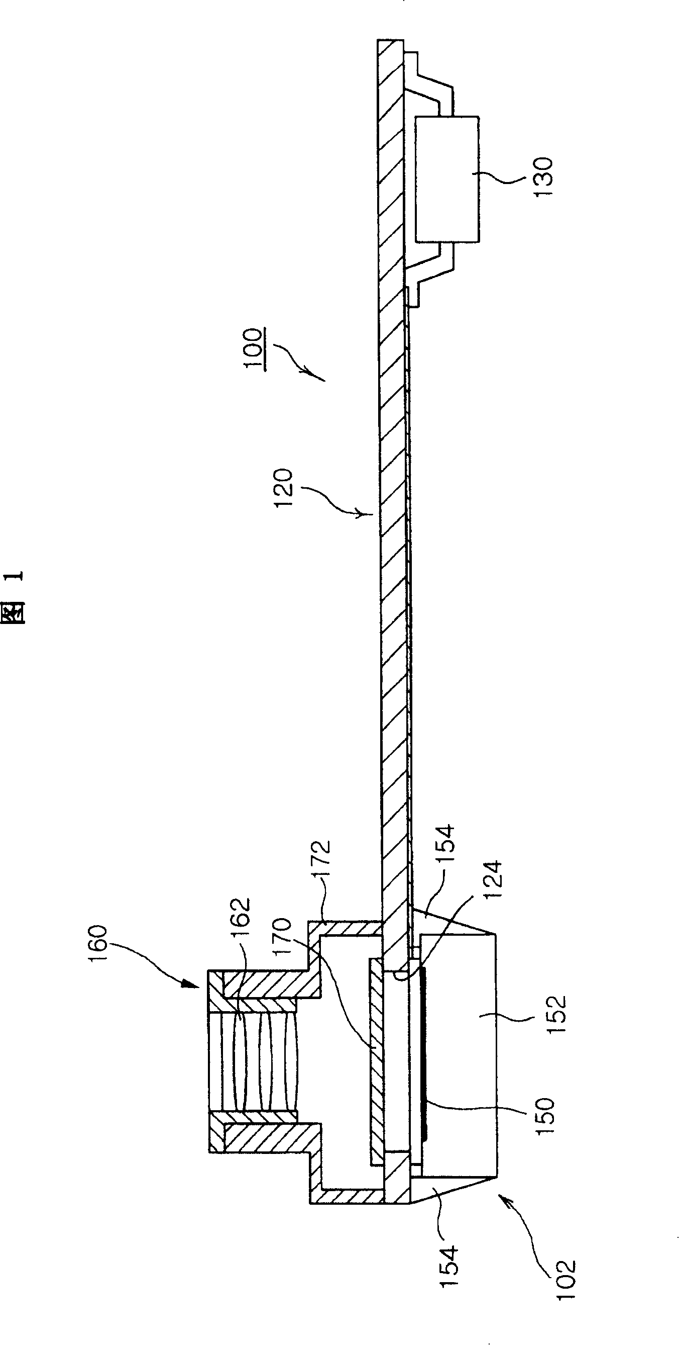
[0027] refer to image 3 , the lens unit 1 for a camera module having an optical filter therein according to the present invention is provided to the image sensor unit 102 of the camera module 100 to transmit light to the image sensor 152 .

[0028] The lens unit 1 includes a housing 10 having a cavity therein. The case 10 has a cylindrical structure with a light receiving hole 12 formed at one side thereof.

[0029] refer to image 3 , the housing 10 has an outer diameter that can be installed in the housing 172 of the image sensor unit 102 . Of course, the housing 10 does not have to be cylindrical, but may have a polygonal cross-section depending on the shape of the lens used.

[0030] The present invention arranges a plurality of lenses 15 a and 15 b inside the case 10 for transmitting light that has passed through...


PUM


Abstract

A lens unit for a camera module having an optical filter therein is provided. The lens unit includes a casing, a plurality of lenses, an optical filter, and a fixing member. The casing has a light-receiving hole formed in one side thereof and has a structure in which a cavity is formed. The lenses are aligned in the inside of the casing to transmit light that passes through the light-receiving hole. The optical filter is disposed in the inside of the casing to block a partial wavelength of light and the fixing member maintains the lenses and the optical filter at an aligned state in the inside of the casing. A separate optical filter doesn't need to be mounted in the camera module but is integrally formed in the inside of the casing, so that inflow of foreign substance during the manufacturing process is minimized.

Description

[0001] This application is based upon and claims the benefit of priority from Korean Patent Application No. 2005-8223 filed in the Korean Intellectual Property Office on January 28, 2005, the disclosure of which is hereby incorporated by reference in its entirety. technical field [0002] The present invention relates to a lens unit for a camera module used in a camera system of a digital optical device, more particularly, the present invention relates to a lens unit for a camera module having an optical filter therein, The lens unit can minimize the introduction of impurities during the manufacturing process, minimize the size of the camera module assembly in which the filter is installed, and minimize the reduction in optical performance, and by integrally forming the filter in the case The manufacturing process is simplified internally without separately mounting the filter on the camera module. Background technique [0003] Currently, many companies develop and produce c...

Claims


Application Information

Patent Timeline
Patent Type & Authority Patents(China)
IPC IPC(8): H04N5/225G02B7/00G02B7/02G03B11/00
CPCH04N5/2254G03B7/099Y02E60/10G01B7/16G01M5/0008H01M10/465
Inventor 金好兼南亨佑
Owner SAMSUNG ELECTRO MECHANICS CO LTD
Why Eureka
Try Eureka