Cooling apparatus

A technology of cooling equipment and cooling state, applied in lighting and heating equipment, refrigerators, refrigeration components, etc., can solve problems such as damage to equipment, uncertainty of high-pressure side pressure, and reduction of cooling efficiency

Inactive Publication Date: 2007-08-08
SANYO ELECTRIC CO LTD
View PDF1 Cites 7 Cited by
  • Summary
  • Abstract
  • Description
  • Claims
  • Application Information

AI Technical Summary

Problems solved by technology

[0007] However, if carbon dioxide is used as the refrigerant, the high pressure side of the refrigeration circuit may become supercritical
Therefore, the high side pressure cannot be determined due to the external air temperature, especially at startup or when the external air temperature is hi

Method used


Image

  • Cooling apparatus
  • Cooling apparatus
  • Cooling apparatus

Examples


Embodiment Construction

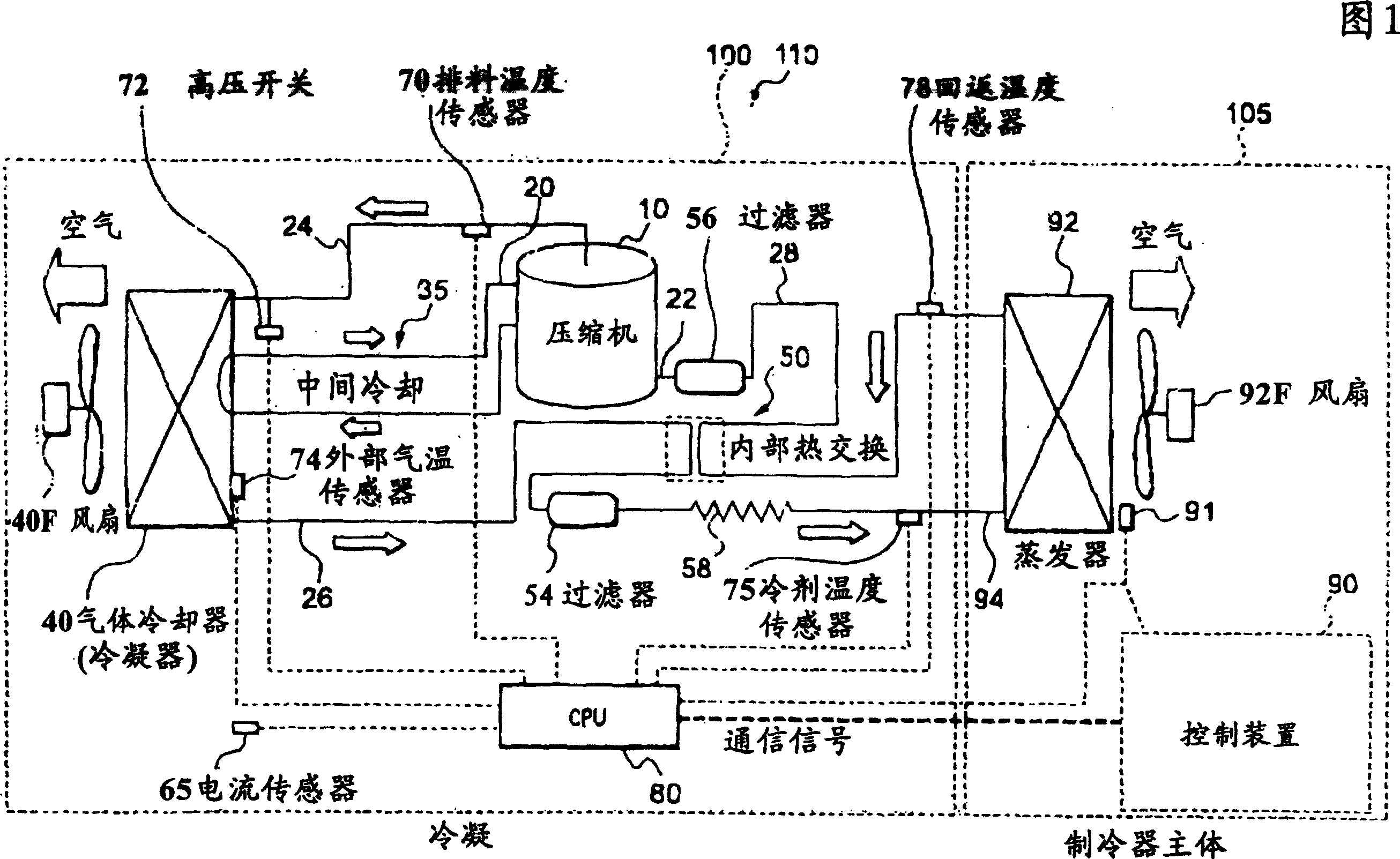
[0024] Next, preferred embodiments of the present invention will be described in detail with reference to the accompanying drawings. The cooling device 110 of FIG. 1 includes a condensing unit 100 and a refrigerator body 105 which becomes a cooler body. The cooling device 110 of this embodiment is, for example, a showcase installed in a store. Thus, the refrigerator main body 105 is constituted by the adiabatic wall of the showcase.

[0025] The condensing unit 100 includes a compressor 10, a gas cooler (condenser) 40, a capillary tube 58, and the like, and includes an evaporator 92 connected to a refrigerator main body 105 (described later) via a conduit. The compressor 10, the gas cooler 40 and the capillary tube 58 together with the evaporator 92 constitute a predetermined refrigeration circuit.

[0026] That is, the refrigerant discharge pipe 24 of the compressor 10 is connected to the inlet of the gas cooler 40 . Here, according to the present embodiment, the compresso...


PUM


Abstract

The invention provides a cooling apparatus which can improve a cooling efficiency while preventing an abnormal increase in pressure of a high side. The cooling apparatus comprises: a refrigerant circuit which uses carbon dioxide as a refrigerant; a control device which controls a speed of rotation of the compressor between predetermined lowest and highest speeds; and a cooled state sensor which detects a cooled state in a refrigerator main body to be cooled by an evaporator included in the refrigerant circuit, wherein the control device sets the target evaporation temperature of the refrigerant of the evaporator according to the cooling space temperature detected by the cooling sensor, and controls the rotary speed of the control compressor so that the evaporation temperature of the refrigerant is set to equal the target evaporation temperature of the evaporation.

Description

[0001] This application is a divisional application of the invention patent application "cooling equipment" with the filing date of May 28, 2004 and the application number of 200410047271.9. technical field [0002] The invention relates to a cooling device equipped with a refrigeration circuit comprising a compressor capable of controlling the rotational speed and using carbon dioxide as refrigerant. Background technique [0003] In such a conventional cooling device such as a display cabinet installed in a store, the compressor, the gas cooler (condenser) and the barrier device (capillary tube, etc.) constituting the condensing unit are sequentially connected to the The evaporators on the main body of the cabinet are connected to form a refrigeration circuit. Refrigerant gas compressed by the compressor to increase in temperature and pressure is discharged to the gas cooler. The heat is dissipated from the refrigerant gas in the gas cooler, which is then trapped by the ba...

Claims


Application Information

Patent Timeline
IPC IPC(8): F25B9/00F25B49/02F25B1/00
Inventor 山崎晴久松本兼三石垣茂弥山中正司山口贤太郎
Owner SANYO ELECTRIC CO LTD
Why Eureka
Try Eureka