Refrigeration heat pump unit of carbon dioxide (CO2) transcritical cycle and control method thereof

A heat pump unit, transcritical technology, applied in refrigerators, refrigeration components, heat pumps, etc.

Inactive Publication Date: 2013-05-15
秦海涛
View PDF5 Cites 11 Cited by
  • Summary
  • Abstract
  • Description
  • Claims
  • Application Information

AI Technical Summary

Problems solved by technology

[0003]The transcritical CO2 refrigeration system in the prior art mainly includes a compressor, a cooler, a regenerator, a throttle valve, a gas Liquid separator, evaporator, etc., the deficiency of the transcritical CO2 refrigeration system in the prior art is: when the environment of the system changes, the refrigerant distribution in the system will change, due to The high-temperature and high-pressure CO2 refrigerant in the gas cooler cannot be liquefied, resulting in the refrigerant distribution in each component having a great influence on the system pressure, and it is difficult to adjust the high and low pressure of the refrigeration system; due to the transcritical CO The temperature and pressure of 2 are not in one-to-one correspondence. The supercritical CO2 releases heat in the cooler, and the temperature changes greatly. The large temperature difference between the inlet and outlet of the cooler makes the span The critical cycle efficiency is improved, and different outlet temperatures correspond to an optimal cooling pressure to maximize cycle efficiency
Therefore, when the ambient temperature changes and the outlet temperature of the gas cooler changes, the cooling pressure cannot be adjusted accordingly to ensure that the refrigeration system has a high coefficient of performance, and unlike the subcritical cycle, the cooling pressure does not exceed The lower the better, but there is an optimal value for different outlet temperatures, so it is difficult to adjust

Method used


Image

  • Refrigeration heat pump unit of carbon dioxide (CO2) transcritical cycle and control method thereof

Examples


Embodiment Construction

[0017] Hereinafter, the present invention will be described in detail with reference to the drawings and examples.

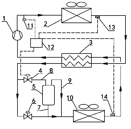
[0018] transcritical CO 2 Refrigerant refrigeration heat pump unit including CO 2 Refrigerant compressor 1, gas cooler 2, regenerator 3, throttle valve I4, gas-liquid separator 5, throttle valve II6, evaporator 10, controller 12, pressure sensor 11, temperature sensor 13 and superheated temperature The sensor 14 and the components are connected into a closed system through pipelines: the exhaust port of the compressor 1 is connected with the inlet of the gas cooler 2, the outlet of the gas cooler 2 is connected with the inlet I of the regenerator 3, and the outlet I of the regenerator 3 is divided into two One way is connected to the inlet of the evaporator after passing through the throttle valve Ⅱ6, the other way is connected to the inlet of the gas-liquid separator 5 through the throttle valve Ⅰ4, and the outlet pipe at the top of the gas-liquid separator 5 ...


PUM


Abstract

The invention belongs to the technical field of transcritical carbon dioxide (CO2) refrigeration heat pumps. A refrigeration heat pump unit of a CO2 transcritical cycle comprises a CO2 refrigerant compressor, a gas cooler, a regenerator, a throttle valve I, a gas-liquid separator, a throttle valve II, an evaporator, a controller, a pressure sensor, a temperature sensor and a superheat temperature sensor. All parts are connected through pipelines to form a closed system. The controller controls opening degrees of the throttle valve I and the throttle valve II according to detected refrigerant pressure in the gas cooler, detected refrigerant temperature of an outlet of the gas cooler, refrigerant superheat degree of an outlet of the evaporator and the highest cooling pressure Pg of system operation, and the unit is enabled to be operated under high cycling efficiency. The refrigeration heat pump unit of the CO2 transcritical cycle and a control method of the refrigeration heat pump unit of the CO2 transcritical cycle have the advantages that when environment temperature or environment temperature of a cooled department changes, the controller can adjust the unit and enable the unit to be operated under the high cycling efficiency, and the method is simple, easy to achieve, reliable and stable.

Description

technical field [0001] The present invention belongs to transcritical CO 2 Refrigeration heat pump technology field. Background technique [0002] Due to the important impact of CFCs on the ozone layer and atmospheric warming, protecting the environment and realizing the replacement of CFCs has become a common concern all over the world. As a substitute for CFCs, HFCs refrigerants do not destroy the ozone layer, but their obvious greenhouse effect still has a certain impact on environmental warming. As a result, people began to strongly advocate the use of natural refrigerants. CO 2 Natural refrigerants have received extensive attention again, CO 2 The research and application of refrigeration and heat pump devices has once again become a hot spot that has attracted worldwide attention. [0003] Transcritical CO in prior art 2 The refrigeration system mainly includes compressors, coolers, regenerators, throttle valves, gas-liquid separators, evaporators, etc. The exist...

Claims


Application Information

Patent Timeline
Patent Type & Authority Applications(China)
IPC IPC(8): F25B30/02F25B41/06F25B49/02F25B41/30
Inventor 秦海涛
Owner 秦海涛
Why Eureka
Try Eureka