
Method for forming long tube part with partial convexity
A technology of local protrusions and parts, applied in the direction of forming tools, manufacturing tools, engine components, etc., can solve the problems of poor strength and rigidity of parts, unreachable overall performance, complicated production process, etc., to reduce deformation resistance and save equipment The effect of investment and saving mold cost
- Summary
- Abstract
- Description
- Claims
- Application Information
AI Technical Summary
Problems solved by technology
Method used
Image

Examples
specific Embodiment approach 1
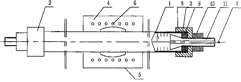
[0020] Specific implementation mode one: combine figure 1 The present embodiment will be described. The steps of the forming method of the long tube parts with local protrusions in this embodiment are as follows:
[0021] Step 1. First, seal the two ends of the pipe 1 with the sealing device 2. The sealing device 2 is composed of a constraining ring 8, an elastic ring 9, a nut 10 and a tie rod 11 with a tapered surface. The constraining ring 8 is set on the end of the pipe 1. On the tie rod 11 with a tapered surface, the restraining ring sleeve 8 is connected with the pipe 1 through the thread 3, the elastic ring 9 is arranged on the inner wall of the end of the pipe 1 and the outer circumference of the tie rod 11 with a tapered surface, and the nut 10 is arranged on the restraining ring sleeve 8 On the tapered tie rod 11 at the outer end, the axis of the tapered tie rod 11 is provided with a pressure medium channel 7, and the tapered end of the tapered tie rod 11 is arranged...
specific Embodiment approach 2
[0026] Specific implementation mode two: combination figure 1 The present embodiment will be described. The heating device 6 of this embodiment adopts the heating method of electric heating rod or hot oil circulation.
specific Embodiment approach 3
[0027] Specific implementation mode three: combination figure 1 The present embodiment will be described. The elastic ring 9 of this embodiment is made of polyurethane material.
PUM
| Property | Measurement | Unit |
|---|---|---|
| yield strength | aaaaa | aaaaa |
Abstract
Description
Claims
Application Information