Dust collecting container for electric vacuum cleaner

A technology for vacuum cleaners and containers, applied in the directions of vacuum cleaners, suction filters, applications, etc., can solve problems such as spilling and soiling of the ground, and achieve the effect of suppressing the reduction of attractive force and improving the dust collection ability.

Inactive Publication Date: 2008-08-13
SANYO ELECTRIC CO LTD
View PDF1 Cites 2 Cited by
  • Summary
  • Abstract
  • Description
  • Claims
  • Application Information

AI Technical Summary

Problems solved by technology

Therefore, when removing the filter in order to throw away the dust accumulated in the dust collection chamber, the opposite surface of the filter must of course be made upward, and if the opposite surface is not made horizontal, the surface on the opposite surface The dust will be scattered inadvertently, resulting in the undesirable situation of dirtying the ground

Method used


Image

  • Dust collecting container for electric vacuum cleaner
  • Dust collecting container for electric vacuum cleaner
  • Dust collecting container for electric vacuum cleaner

Examples


Embodiment Construction

[0101] Next, specific embodiments of the present invention will be described with reference to the drawings.

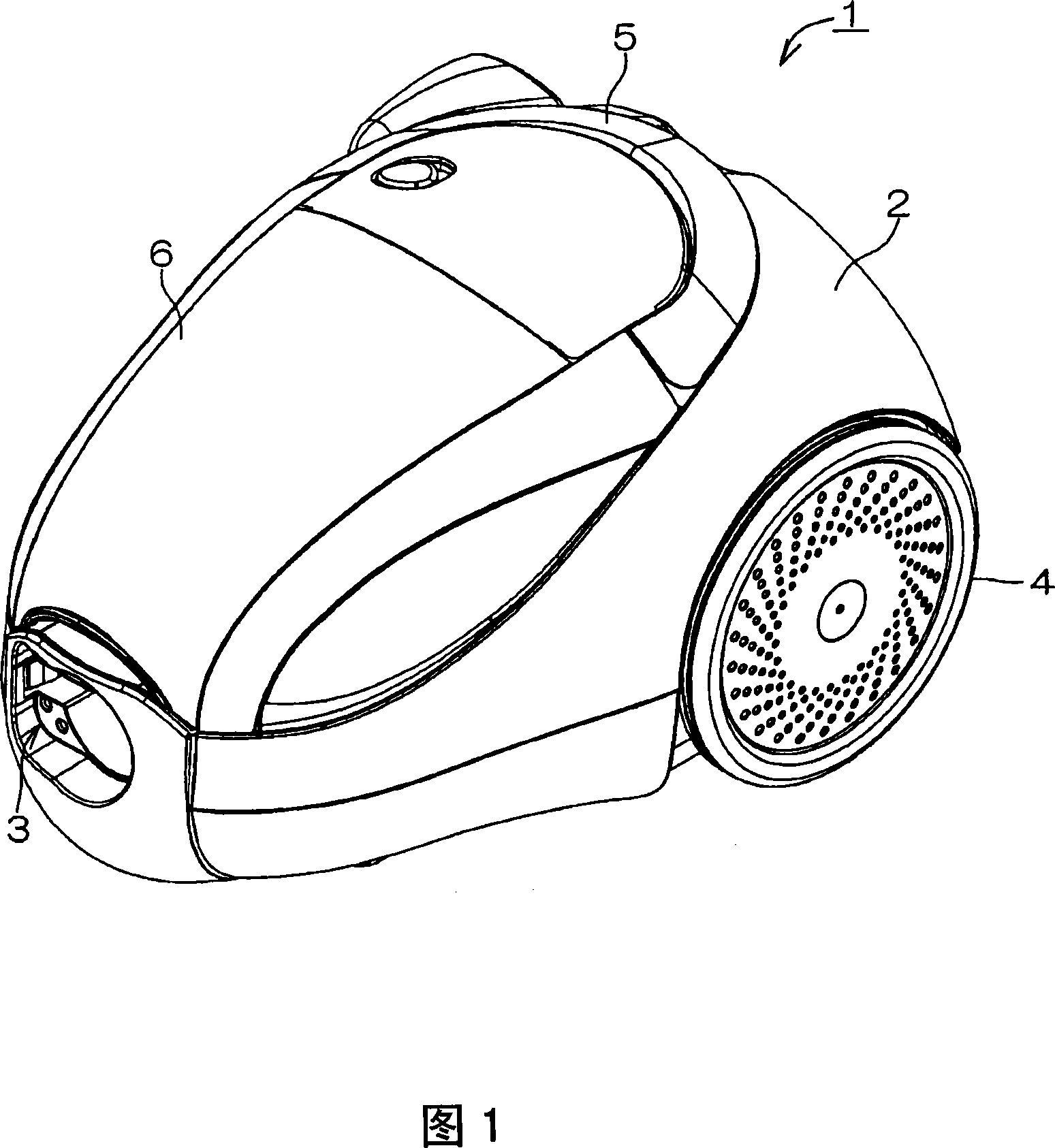
[0102] Fig. 1 is a perspective view of a vacuum cleaner main body 1 according to an embodiment of the present invention. In the electric vacuum cleaner main body 1 shown in FIG. 1 , the left obliquely lower side is referred to as the front, and the right obliquely upper side is referred to as the rear. Up and down are also specified according to this direction.

[0103] The main body 1 is defined by, for example, a case 2 formed of resin, and a suction hose attachment hole 3 is formed in the front of the case 2 . In addition, wheels 4 with relatively large diameters are installed on the left and right sides near the rear of the casing 2 . In addition, a handle 5 that can be erected from the illustrated folded state to an erected state is provided on the upper surface of the housing 2 . An openable and closable cover 6 is disposed on the front side of the handle 5 ....


PUM


Abstract

The present invention provides a dust collecting container for an electric dust collector, capable of successfully throwing away the dust without ensuring the dust of a dust collecting container fall obliviously. In the dust collecting container, a filter has a main plane opposite to an outer shell, and a side standing from the end of the main plane to the cross direction of the main plane, a storage part for storing dust formed by the main plane and the side. The storage part forms a dish shape having a bottom, which is formed by the main plane and the side. Thus, in order to throwing away the dust in the storage part, the filter is discharged from the outer shell, even if the storage is not horizontal, the dust in stored in the storage part is obliviously thrown away, throwing away successfully.

Description

technical field [0001] The present invention relates to a dust collecting container of an electric vacuum cleaner. Background technique [0002] Generally, an electric vacuum cleaner houses an electric blower and a dust collection container in its main body, and absorbs dust by the suction force generated when the electric blower is driven, and the dust is captured by the dust collection container (see Patent Document 1). [0003] The dust collecting container described in Patent Document 1 is provided with a dust collecting chamber (corresponding to a casing) in which an air inlet and an opening are formed. A filter is disposed in the opening so as to close the opening. In this dust collection container, dust and air are taken into the dust collection chamber through the suction port by the suction force of the electric blower. Then, the air and dust taken into the dust collection chamber are separated by the filter. That is, dust is captured by the filter and accumulate...

Claims


Application Information

Patent Timeline
Patent Type & Authority Applications(China)
IPC IPC(8): A47L9/10A47L9/14
CPCA47L9/122A47L9/1608
Inventor 土田英也森田明宏
Owner SANYO ELECTRIC CO LTD
Why Eureka
Try Eureka