Pipes shaping limit curve test device for hydraulic bulging process

A forming limit curve and hydraulic bulging technology, which is applied in the field of mechanical engineering, can solve problems such as the inability to effectively realize the linear strain path, the inability to change the strain state, and the inability to obtain the forming limit curve.

Inactive Publication Date: 2008-10-15
SHANGHAI JIAO TONG UNIV
View PDF0 Cites 12 Cited by
  • Summary
  • Abstract
  • Description
  • Claims
  • Application Information

AI Technical Summary

Problems solved by technology

It can be seen from the figure that in the biaxial tensile strain state, the linear strain path cannot be effectively rea

Method used


Image

  • Pipes shaping limit curve test device for hydraulic bulging process
  • Pipes shaping limit curve test device for hydraulic bulging process

Examples


Embodiment 1

[0018] The device in this embodiment is an experimental device for measuring the forming limit curve under tension-compression strain state, and can measure the forming limit of the material when the strain ratio varies between -1 and 0.

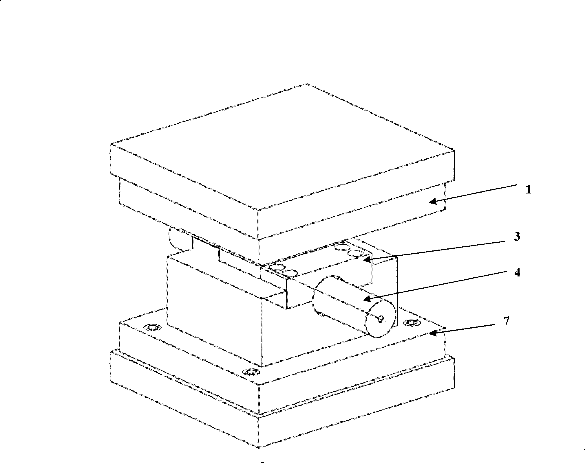
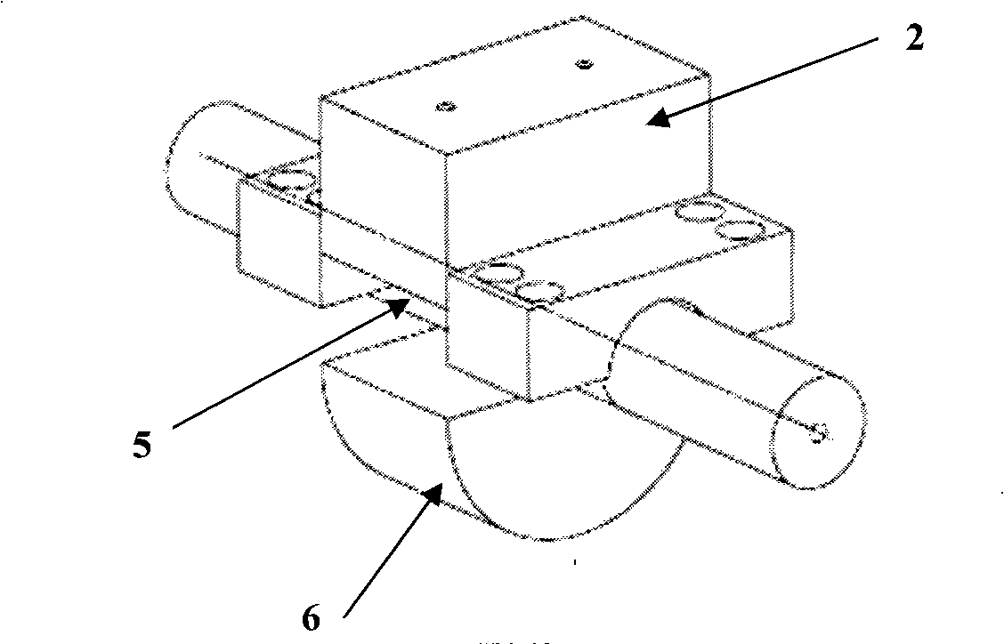
[0019] Such as figure 1 and figure 2 Shown, the present embodiment is made up of patrix, counterdie and push rod.

[0020] Upper die is made up of upper connecting plate 1 and upper insert 2. The upper connecting plate 1 is connected to the hydraulic bulging machine by screws. The upper insert 2 is connected with the upper connecting plate 1 by screws, the lower surface thereof is a plane, and there is no transition fillet between the bottom surface and the side surface.

[0021] Lower mold is made up of fixed block 3, lower insert 6 and lower mold 7. Lower mold 7 is fixed on the workbench of hydraulic bulging machine. The lower insert 6 is arranged in the cavity of the lower mold 7 . There are two fixed blocks 3 connected to the lowe...

Embodiment 2

[0036] This embodiment is an experimental device for measuring the forming limit curve under the state of tension-tension strain, which can measure the forming limit of the material when the strain ratio varies between 0 and 1.

[0037] Such as figure 1 and figure 2 Shown, the present embodiment is made up of patrix, counterdie and push rod.

[0038] The upper die is composed of an upper connecting plate 1 and an upper insert 2, and the upper connecting plate 1 is connected to the hydraulic bulging machine by screws. The upper insert 2 is connected with the upper connecting plate 1 by screws, the lower surface thereof is a plane, and there is a transitional fillet between the bottom surface and the side surface.

[0039]Lower mold is made up of fixed block 3, lower insert 6 and lower mold 7. Lower mold 7 is fixed on the workbench of hydraulic bulging machine. The lower insert 6 is arranged in the cavity of the lower mold 7 . There are two fixed blocks 3 connected to the ...


PUM


Abstract

The invention relates to a testing device for a tube forming limit curve used for the hydraulic bulging technique in the mechanical engineering technical field, comprising an upper die, a lower die and a push rod, wherein, the upper die comprises an upper connecting plate and an upper insert block; the upper connecting plate is connected to a main cylinder of a hydraulic bulging machine; the upper insert block is fixed on the upper connecting plate and positioned through a pin stop; the lower die comprises fixed blocks, a lower die set and a lower insert block; the lower die set is fixed on a worktable of the hydraulic bulging machine and adopts a symmetrical structure; both ends of the lower die set have semi-cylindrical die cavities; the lower insert block is fixed inside a lower die set die cavity; the number of the fixed blocks is two; a semi-cylindrical die cavity is arranged on each fixed block; and the two fixed blocks are fixed on both ends of the lower die set and form two cylindrical die cavities respectively with the two semi-cylindrical die cavities of the lower die set. The testing device not only can make a tube be able to deal with path distortion with linearity or quasi-linearity and reach the state of limit strain but also can make the strain ratio change between -1 and 1.

Description

technical field [0001] The invention relates to a testing device in the technical field of mechanical engineering, in particular to a testing device for a pipe forming limit curve of a hydraulic bulging process. Background technique [0002] Hydraulic bulging of pipe fittings is a technology that makes the outer wall of the tube blank fit the inner surface of the mold cavity through internal pressure and axial force feeding. Using the hydraulic bulging technology of pipe fittings, the pipe blank placed in the mold can be formed into hollow parts of various cross-sectional shapes through the action of high-pressure liquid. Compared with the traditional stamping-welding process, the use of hydraulic bulging technology to process hollow parts has the advantages of reducing weight, saving materials, reducing the number of parts and molds, reducing mold costs, reducing the amount of subsequent machining and assembly welding, and improving the strength and rigidity of parts, etc. ...

Claims


Application Information

Patent Timeline
IPC IPC(8): G01N3/28
Inventor 林忠钦来新民于忠奇徐祥合武志刚
Owner SHANGHAI JIAO TONG UNIV
Why Eureka
Try Eureka